Supercharge Your Innovation With Domain-Expert AI Agents!

Image displaying device and method, and image processing device and method for preventing image deterioration

a technology of image deterioration and display image, which is applied in the direction of instruments, television systems, signal generators with optical-mechanical scanning, etc., can solve the problems of motion blur, out of focus outline of moving parts, and worsening time frequency characteristics, so as to prevent deterioration in image quality of display image effectively

Inactive Publication Date: 2013-09-17
SHARP KK
View PDF43 Cites 1 Cited by
  • Summary
  • Abstract
  • Description
  • Claims
  • Application Information

AI Technical Summary

Benefits of technology

The present invention prevents the image quality of a display image from deteriorating when special reproduction techniques are used. This is achieved by not performing interpolation processing through motion compensation.

Problems solved by technology

As compared to a CRT (Cathode Ray Tube) that has been mainly used for the purpose of realizing moving images, an LCD (Liquid Crystal Display) has a drawback, that is, a motion blur, that when displaying an image in motion, outline of a moving part is perceived by a viewer out of focus.
In the hold-type display system as described above, since impulse response of image display light has a temporal spread, time frequency characteristics are worsened with the deterioration of space frequency characteristics, accompanied and therefore a motion blur occurs.
That is, since human eyes smoothly follow a moving object, when the light emission time is long like in the case of the hold type, motion of an image looks jerky and unnatural due to a time integration effect.
However, in the case of frame interpolation processing by linear interpolation, unnaturalness (jerkiness, judder) accompanying frame rate conversion occurs, and the motion blur interference caused by the above-described hold-type display system, can not be sufficiently improved, and therefore, it is impossible to achieve sufficient image quality.

Method used


Image

  • Image displaying device and method, and image processing device and method for preventing image deterioration
  • Image displaying device and method, and image processing device and method for preventing image deterioration
  • Image displaying device and method, and image processing device and method for preventing image deterioration

Examples


first embodiment

[0106]In a first embodiment of the present invention, when an input image signal is an image signal obtained by special reproduction including “fast forward reproduction”, “rewind reproduction”, “slow reproduction”, and “frame advance reproduction”, for example, in a video reproducing device, an output of the motion vector detecting portion 11e is made to zero-vector forcibly in order to make the motion compensation processing in the FRC portion 10 ineffective.

[0107]FIG. 6 is a block diagram showing an example of the structure of the essential parts of a liquid crystal displaying device according to the first embodiment of the present invention, and the liquid crystal displaying device comprises a FRC portion 10, a special reproduction determining portion 14, a controlling portion 15, a switching portion 16, a zero-vector portion 17, an electrode driving portion 18, and a liquid crystal display panel 19. The switching portion 16 is provided between the motion vector detecting portio...

second embodiment

[0117]In a second embodiment of the present invention, when an input image signal is an image signal obtained by special reproduction including “fast forward reproduction”, “rewind reproduction”, “slow reproduction”, and “frame advance reproduction” in a video reproducing device, for example, an interpolation vector from the interpolation vector evaluating portion 11f is made to zero-vector so as not to cause interpolation between pixels at different positions in order to make motion compensation processing in the FRC portion 10 ineffective.

[0118]FIG. 7 is a block diagram showing an example of the structure of the principle part of a liquid crystal displaying device according to the second embodiment of the present invention, and the liquid crystal displaying device comprises the FRC portion 10, the special reproduction determining portion 14, the controlling portion 15, the switching portion 16, the zero-vector portion 17, the electrode driving portion 18, and the liquid crystal di...

third embodiment

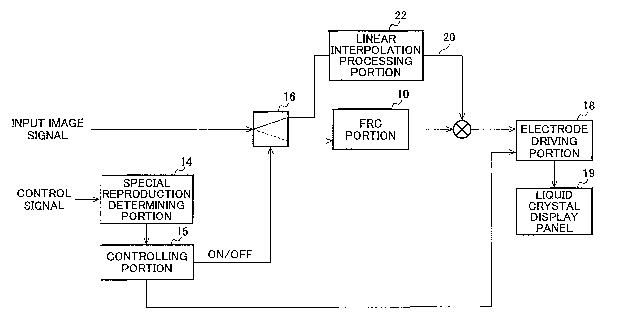
[0121]In a third embodiment of the present invention, a path for bypassing the FRC portion 10 is provided, and when an input image signal is an image signal obtained by special reproduction including “fast forward reproduction”, “rewind reproduction”, “slow reproduction”, and “frame advance reproduction” in a video reproducing device, for example, the input image signal is input to the bypass side to change a driving frequency of the liquid crystal display panel 19 in accordance with a frame frequency of the input image signal. That is, when an image signal obtained by special reproduction is input, the frame rate conversion is not performed and the input image signal is output to the liquid crystal display panel 19 to be displayed as it is.

[0122]FIG. 8 is a block diagram showing an example of the structure of the essential parts of a liquid crystal displaying device according to the third embodiment of the present invention, and the liquid crystal displaying device is comprises the...


PUM


Abstract

Deterioration in image quality of a moving image obtained by special reproduction caused by frame rate conversion (FRC) processing of a motion compensation type is prevented. An image displaying device includes an FRC portion 10 that converts the number of frames of the input image signal by interpolating an image signal to which motion compensation processing has been performed between frames of an input image signal, a special reproduction determining portion 14 that determines whether or not the input image signal is an image signal relating to a predetermined genre, and a controlling portion 15. The FRC portion 10 includes a motion vector detecting portion lie that detects a motion vector between frames of the input image signal, an interpolation vector evaluating portion 11f that assigns an interpolation vector between frames based on the motion vector information, and an interpolation frame generating portion 12d that generates an interpolation frame from the interpolation vector. When the input image signal is an image signal obtained by special reproduction including “fast forward reproduction” and “rewind reproduction”, the controlling portion 15 makes the motion compensation processing in the FRC portion 10 ineffective by making the motion vector detected by the motion vector detecting portion 11e to zero-vector.

Description

TECHNICAL FIELD[0001]The present invention relates to an image displaying device having a function for converting a frame rate or a field rate and a method thereof, and an image processing device and a method thereof, and more specifically to an image displaying device for preventing the deterioration in image quality of moving images obtained by a special reproduction that is caused by rate conversion processing of a motion compensation type, and an image displaying method by the device, and an image processing device and an image processing method by the device.BACKGROUND OF THE INVENTION[0002]As compared to a CRT (Cathode Ray Tube) that has been mainly used for the purpose of realizing moving images, an LCD (Liquid Crystal Display) has a drawback, that is, a motion blur, that when displaying an image in motion, outline of a moving part is perceived by a viewer out of focus. It is pointed out that the motion blur is caused by a display system itself of the LCD (see, for example, J...

Claims


Application Information

Patent Timeline
Patent Type & Authority Patents(United States)
IPC IPC(8): H04N7/01G09G3/20G09G3/36G09G5/00G09G5/18G09G5/36G09G5/391H04N5/93H04N19/50
CPCH04N9/8042H04N5/783H04N7/0132H04N7/014H04N5/145G09G2320/0261G09G2320/106G09G2340/0435
Inventor UENO, MASAFUMIYAMAMOTO, KENICHIROHYOSHII, TAKASHIFURUKAWA, HIROYUKI
Owner SHARP KK
Features
  • R&D
  • Intellectual Property
  • Life Sciences
  • Materials
  • Tech Scout
  • Unparalleled Data Quality
  • Higher Quality Content
  • 60% Fewer Hallucinations
Learn More