Measuring apparatus and projection exposure apparatus having the same
a technology of measuring apparatus and exposure apparatus, which is applied in the direction of photomechanical apparatus, instruments, printing, etc., can solve the problems of inconvenient measurement of focus, difficult to form both element pattern and registration mark on the reticle, and conventional techniques
- Summary
- Abstract
- Description
- Claims
- Application Information
AI Technical Summary
Benefits of technology
Problems solved by technology
Method used
Image

Examples
first embodiment
[0044]FIG. 5 is a view showing a projection exposure apparatus according to the first preferred embodiment of the present invention. A projection exposure apparatus 10 exposes a circuit pattern formed on a reticle 1 to a substrate 3, such as a wafer, by a step-and-scan method. The projection exposure apparatus 10 is suitable for performing lithography on the order of submicron or quarter microns, or less. As shown in FIG. 5, the projection exposure apparatus 10 includes an illumination apparatus 700, a reticle stage RS with a reticle (also called an original) 1 placed on it, and a projection optical system 2. The projection exposure apparatus 10 also has a substrate stage SS with the substrate 3 placed on it, a focus / tilt detection system 33, an arithmetic processing unit 400 of the focus / tilt detection system 33, an alignment detection optical system 15, and an alignment signal processing system 402 serving as the arithmetic processing unit of the alignment detection optical system...
second embodiment
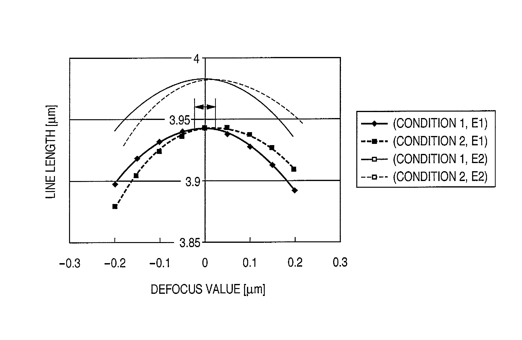
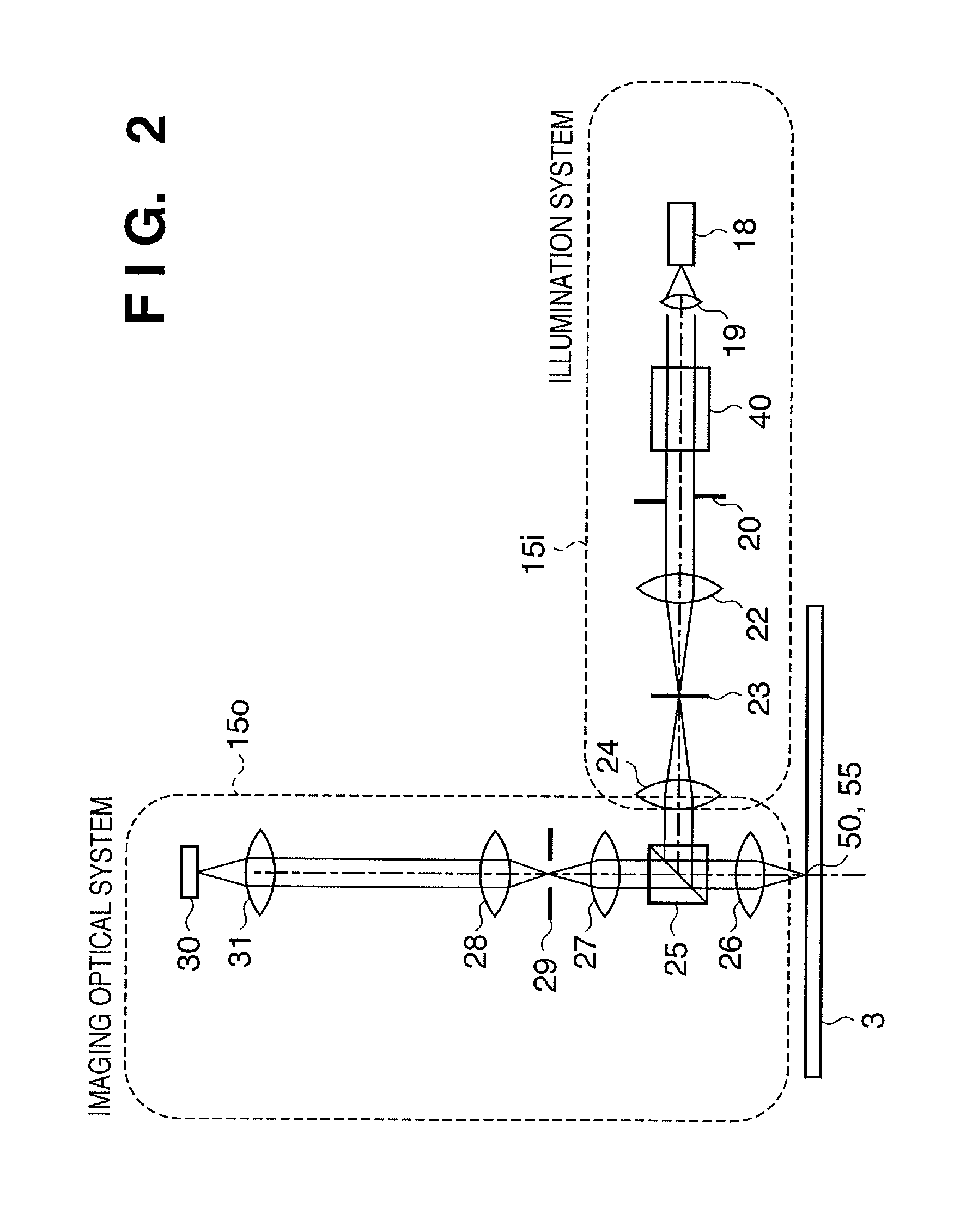
[0085]The second preferred embodiment of the present invention will be described next. As described above, in the characteristic representing the change in the line length measurement value of a registration mark with respect to focus, when the registration mark is measured under different measurement conditions, the focus position representing the extreme value (maximum value) of the line length changes. In the first embodiment, the illumination wavelength of the measuring apparatus is changed to achieve this. In the second embodiment, however, not the illumination wavelength, but the coherence of illumination is changed. The registration mark is the same as that in the first embodiment, and a description thereof will not be repeated. As the measuring apparatus, an alignment scope on a projection exposure apparatus 10 is used. A coherence o can be changed by changing the diameter of an aperture stop 20 in FIG. 2. In this embodiment, line length measurement values L1 and L2 correspo...
third embodiment
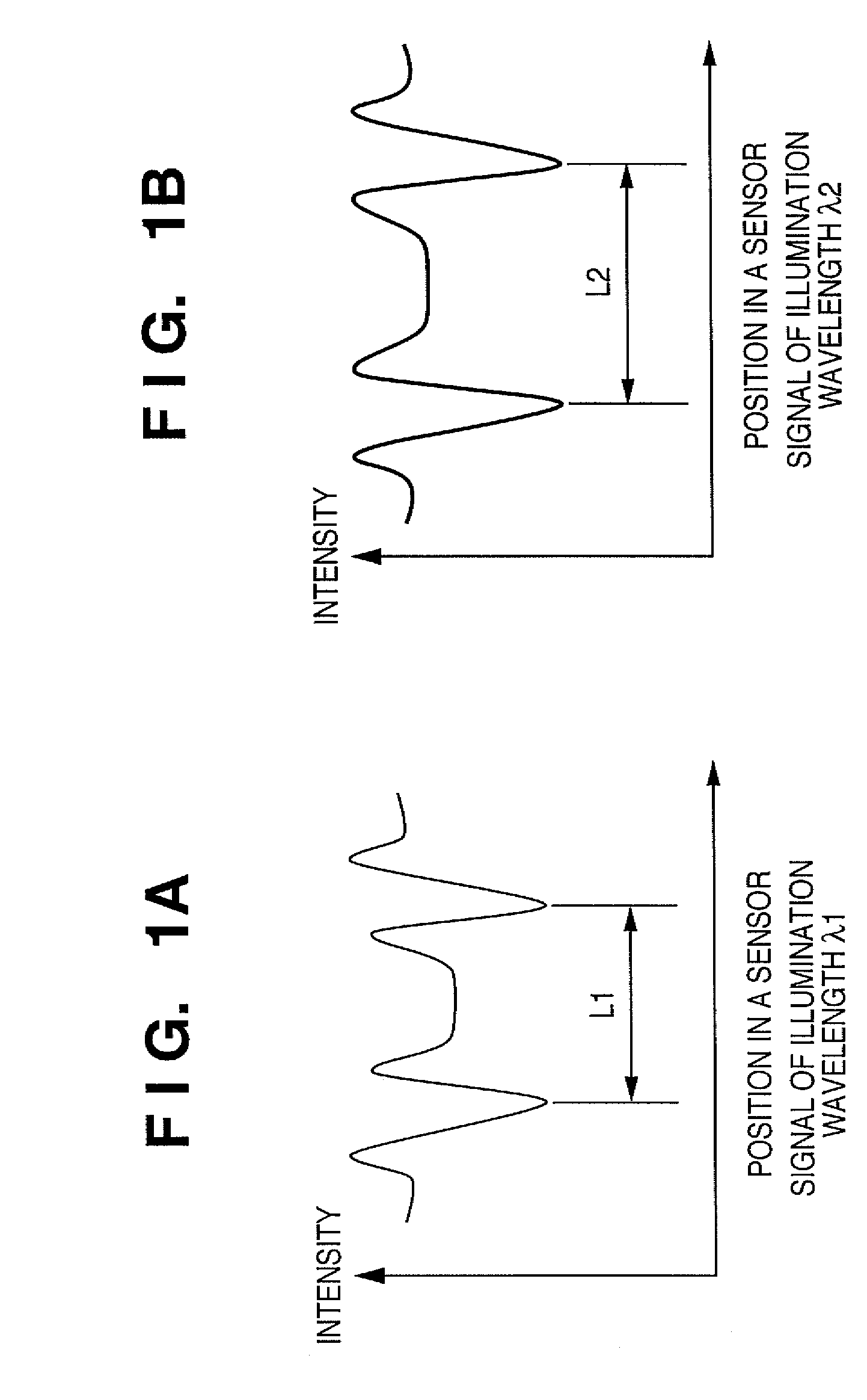
[0087]The third preferred embodiment of the present invention will be described next. In this embodiment, two line length measurement values L1 and L2, depending on edges, are calculated by using a plurality of feature amounts of signal waveforms acquired from one registration mark, to change the focus position representing the extreme value (maximum value) of the line length. FIG. 15 is a graph for explaining a signal waveform, waveform feature amounts, and line length measurement positions, according to this embodiment. A registration mark is measured by the alignment detection system shown in FIG. 2, while fixing the illumination wavelength and the coherence of the illumination system. The interval between the main lobes of the signal waveform generated by the edges of the registration mark is measured as L1, and the interval of the side lobes is measured as L2. In this case, condition 1 corresponds to the interval between the main lobes, and condition 2 corresponds to the interv...
PUM
 Abstract
Description
Claims
Application Information
 - R&D
- Intellectual Property
- Life Sciences
- Materials
- Tech Scout
- Unparalleled Data Quality
- Higher Quality Content
- 60% Fewer Hallucinations
Browse by: Latest US Patents, China's latest patents, Technical Efficacy Thesaurus, Application Domain, Technology Topic, Popular Technical Reports.
© 2025 PatSnap. All rights reserved.Legal|Privacy policy|Modern Slavery Act Transparency Statement|Sitemap|About US| Contact US: help@patsnap.com