Magnetic recording head and magnetic recording/reproducing apparatus

a recording head and recording head technology, applied in the field of magnetic recording/reproducing apparatuses, can solve problems such as element breakag

Inactive Publication Date: 2013-09-17
HITACHI LTD
View PDF6 Cites 27 Cited by
  • Summary
  • Abstract
  • Description
  • Claims
  • Application Information

AI Technical Summary

Benefits of technology

[0018]Problems, structures, and advantageous effects other than those mentioned above will be explained below with reference to embodiments.

Problems solved by technology

When an excessive current applied to the oscillator is increased to improve the spin torque, however, heat generation of an element or migration, as well as element breakage, is caused.

Method used


Image

  • Magnetic recording head and magnetic recording/reproducing apparatus
  • Magnetic recording head and magnetic recording/reproducing apparatus
  • Magnetic recording head and magnetic recording/reproducing apparatus

Examples


first embodiment

[First Embodiment]

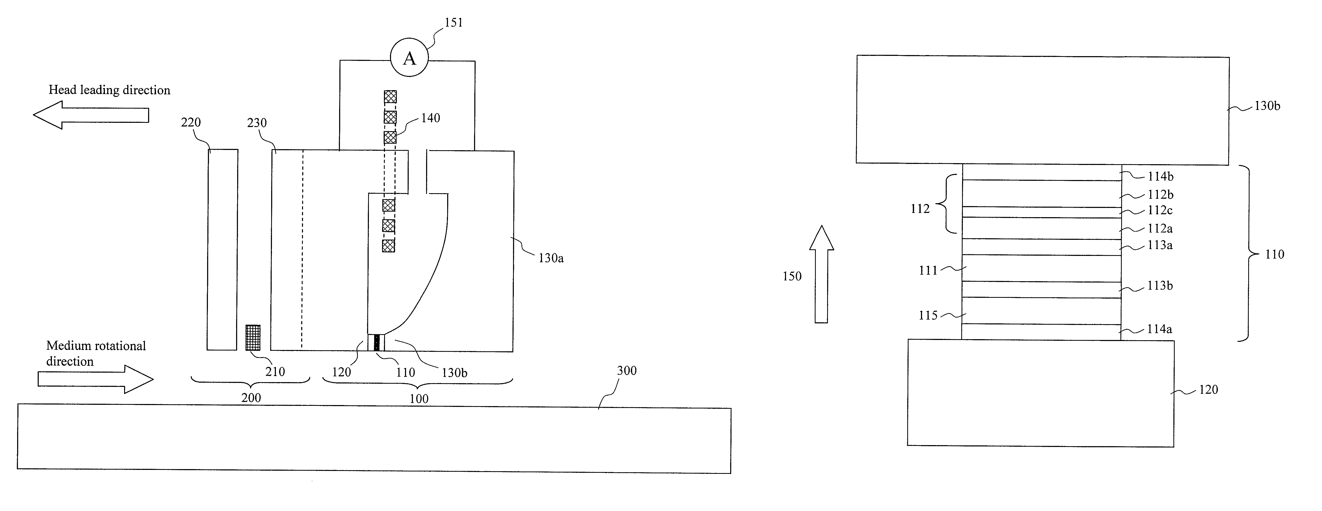
[0030]FIG. 1 is a cross-sectional schematic view showing a magnetic recording (write) / reproducing (read) head according to an embodiment of the present invention. The magnetic recording / reproducing head is a recording / reproducing separation head including a recording head section 100 and a reproducing head section 200. The recording head section 100 includes an oscillator 110 for generating a high frequency magnetic field, a magnetic main pole 120 for generating a magnetic recording field, and a coil 140 and an auxiliary magnetic pole 130a for magnetizing a magnetic field to the magnetic main pole 120. A trailing shield 130b is further provided in a trailing direction of the magnetic main pole 120 according to this embodiment, but the trailing shield is not necessarily provided. The trailing direction is defined as a direction opposite to the leading direction of the head along a medium, and a leading direction is defined as the leading direction of the head along ...

second embodiment

[Second Embodiment]

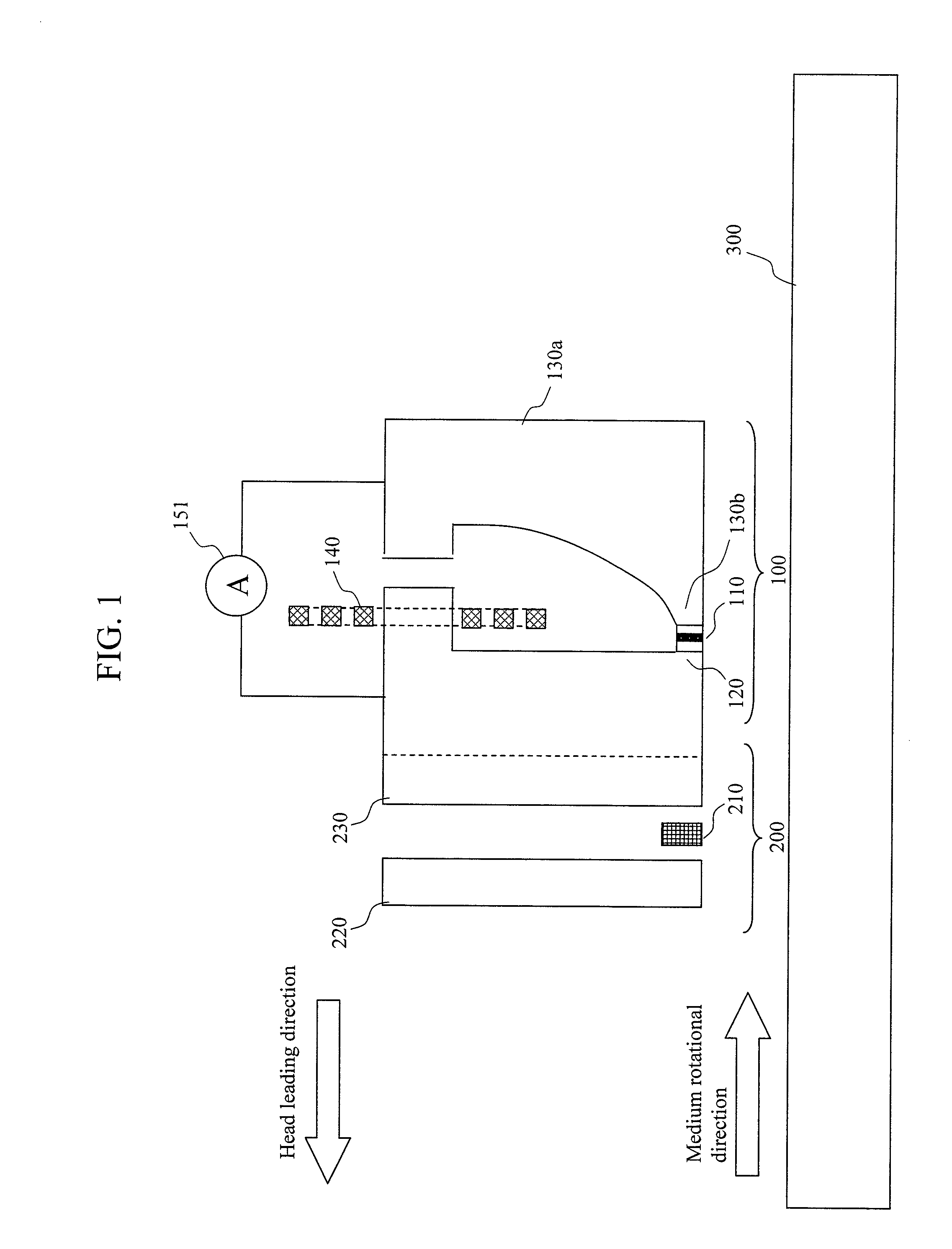
[0048]FIG. 8 shows a magnetic recording / reproducing head according to a second embodiment of the present invention, and is a schematic view of a magnetic main pole, a trailing shield, and an oscillator as viewed from a medium-facing surface.

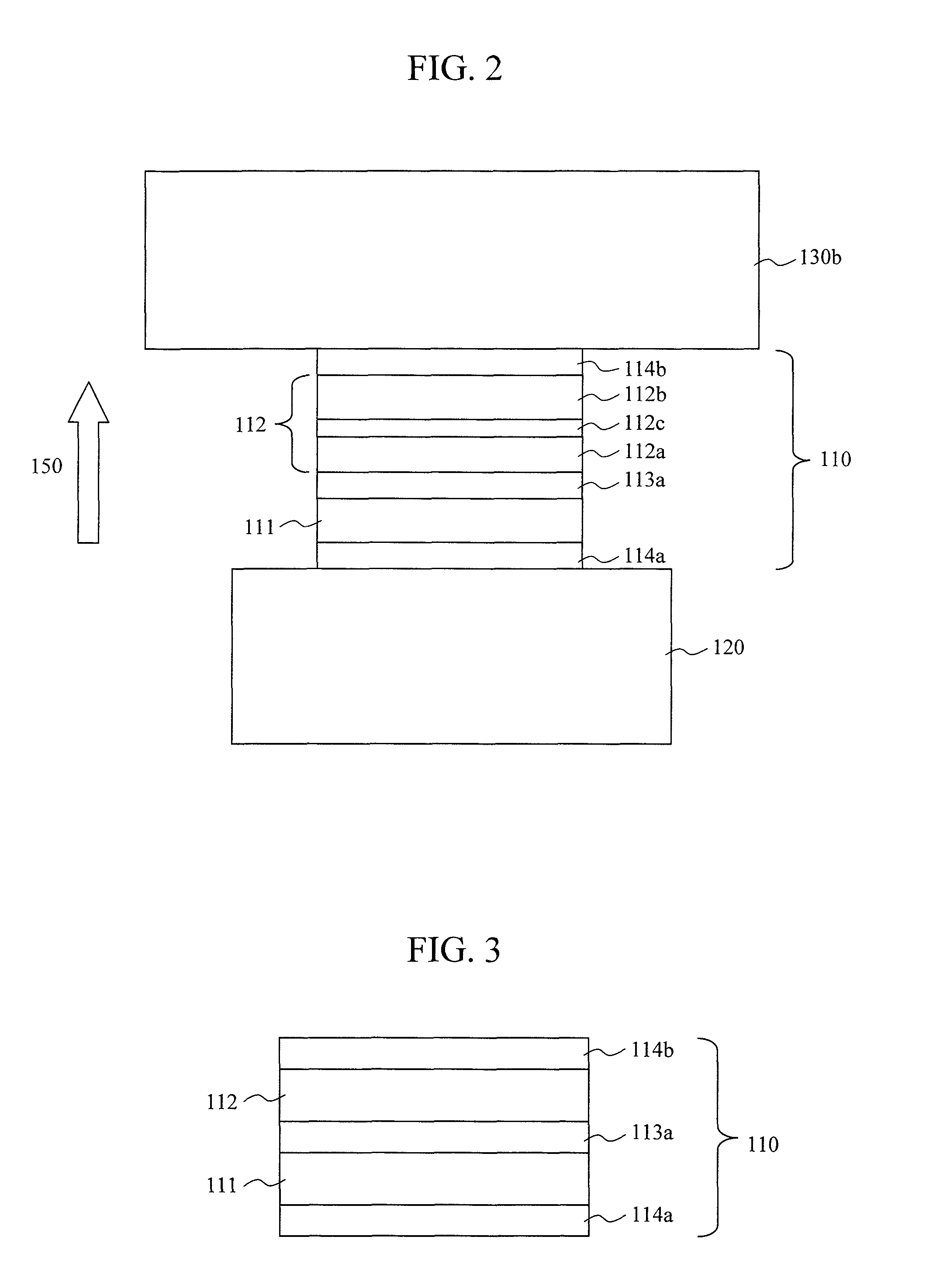
[0049]As compared to the structure shown in FIG. 2, a second spin injection layer structure (SIL2) 115 is provided on the FGL 111 via a second intermediate layer 113b to be opposite to the first spin injection layer structure (SIL1) 112 in which two magnetic layers are coupled to be magnetically anti-parallel each other. The second spin injection layer structure 115 is preferably a structure of a single layer. The second spin injection layer structure 115 may be a structure of laminated layers. At this time, the magnetization of each layer needs to be in the same direction by coupling or the like. Accordingly, when the magnetic gap field is applied, the magnetization direction of the first magnetic layer 112a in the first spin ...

third embodiment

[Third Embodiment]

[0053]FIGS. 10A and 10B are schematic views of a magnetic recording device. FIG. 10A is a top view and FIG. 10B is a cross-sectional view taken along line A-A′.

[0054]The magnetic recording medium (magnetic disk) 300 is fixed to a rotary bearing 404 and rotated by a motor 401. Three magnetic disks and six magnetic heads are illustrated in FIG. 10B, but it is only required that the number of the magnetic disks and the magnetic heads is one or more. The magnetic recording medium 300 is disk-shaped, and has recording layers on both sides. A slider 402 moves on the surface of the rotating recording medium substantially in the radial direction, and includes a magnetic head having the magnetic recording head as explained in the first or second embodiment at the distal end. A suspension 406 is supported by a rotary actuator 403 via an arm 405. The suspension 406 has a function of pushing the slider 402 to the magnetic recording medium 300 or separating the slider 402 from ...


PUM

PropertyMeasurementUnit
frequencyaaaaaaaaaa
thickness t2aaaaaaaaaa

Abstract

In high frequency magnetic assisted recording technique, a spin torque oscillator that stably oscillates at a low current and a magnetic recording head with high recording density are provided. In a magnetic recording head including an oscillator that generates a high frequency magnetic field, a spin injection layer structure of two laminated magnetic layers which are coupled to be anti-parallel is adopted. A product Ms×t of the saturated magnetization Ms and the film thickness t of the first magnetic layer close to a field generation layer is smaller than a product Ms×t of the second magnetic layer remote from the field generation layer.

Description

CLAIM OF PRIORITY[0001]The present application claims priority from Japanese patent application JP 2011-186414 filed on Aug. 29, 2011, the content of which is hereby incorporated by reference into this application.CROSS REFERENCE TO RELATED APPLICATION[0002]U.S. patent application Ser. Nos. 13 / 287,292, 13 / 208,384 and 13 / 296,866 are co-pending applications of this application, the contents of which are incorporated herein by cross-reference.BACKGROUND OF THE INVENTION[0003]1. Field of the Invention[0004]The present invention relates to a magnetic recording head having a function of inducing magnetization switching by applying a high frequency magnetic field to a magnetic recording medium, and a magnetic recording / reproducing device including the magnetic recording head.[0005]2. Background Art[0006]In recent years, recording density of a magnetic recording / reproducing device such as a hard disk drive (HDD) has been requested to increase as fast as 40% per year. The areal recording den...

Claims


Application Information

Patent Timeline
Patent Type & Authority Patents(United States)
IPC IPC(8): G11B5/31G11B5/02G11B5/23
CPCH01L43/08G11B5/3146H01F10/329H01F10/3286H01F10/3272G11B2005/0024H10N50/10
Inventor NAGASAKA, KEIICHISHIIMOTO, MASATOSATO, YO
Owner HITACHI LTD
Why Eureka
Try Eureka