Medical image processing apparatus, method, and program

a technology of medical image and processing apparatus, applied in the field of medical image processing technology, can solve the problems of difficult to observe the distribution of plaques along the center line of blood vessels and how the blood vessels are distributed, and the inability to observe the distribution of plaques over the entire circumference, so as to reduce the time and effort of observation, improve the efficiency of observation, and improve efficiency.

Active Publication Date: 2013-09-17
FUJIFILM CORP
View PDF12 Cites 13 Cited by
  • Summary
  • Abstract
  • Description
  • Claims
  • Application Information

AI Technical Summary

Benefits of technology

[0032]According to the present invention, an index value representing a characteristic of a tubular structure extracted from a three-dimensional medical image may be calculated in each direction of radial visual lines orthogonal to the core line of the tubular structure at each of a plurality of points on the core line with each point as each viewpoint, and a characteristic map image representing the characteristic inside of the tubular structure may be generated by mapping the index value calculated in each direction of the radial visual lines at each point on the core line to a coordinate plane defined by a first coordinate component representing a position in a direction of the core line and a second coordinate component representing a direction of each visual line. This allows obvious visual recognition of the characteristic of the tubular structure in the three-dimensional medical image using the characteristic map image, thereby reducing the time and effort to observe a plurality of images by changing the display range as required in the case in which observation is performed using a convention image (orthogonal cross-section image or CPR image) representing a tubular structure and improving the efficiency of observation. In this way, the present invention may improve efficiency for observing a characteristic of a tubular structure using an image.
[0033]In the present invention, in the case where two types of index values are calculated and a characteristic map image in which each type index value is represented in a coordinate space defined by the first and second coordinate components, and a third coordinate component representing either one of the two types of index values is generated, the characteristic of the tubular structure may be observed from various aspects using a plurality of types of index values, thereby contributing to the observation accuracy.

Problems solved by technology

That is, in the orthogonal cross-section image of the blood vessel, it is possible to know the plaque distribution and state of stenosis in all circumferential directions of the blood vessel at the position of the orthogonal cross-section, but it is difficult to observe how the plaque presents in the depth direction along the center line of the blood vessel and how the blood vessel is narrowed.
In the CPR image of the blood vessel, it is possible to know the plaque distribution and state of stenosis in the depth direction along the center line of the blood vessel, but these are the states in a particular cross-section along the center line of the blood vessel and it is impossible to observe how the plaque is distributed and how the blood vessel is narrowed over the entire circumference of the blood vessel.

Method used


Image

  • Medical image processing apparatus, method, and program
  • Medical image processing apparatus, method, and program
  • Medical image processing apparatus, method, and program

Examples


first embodiment

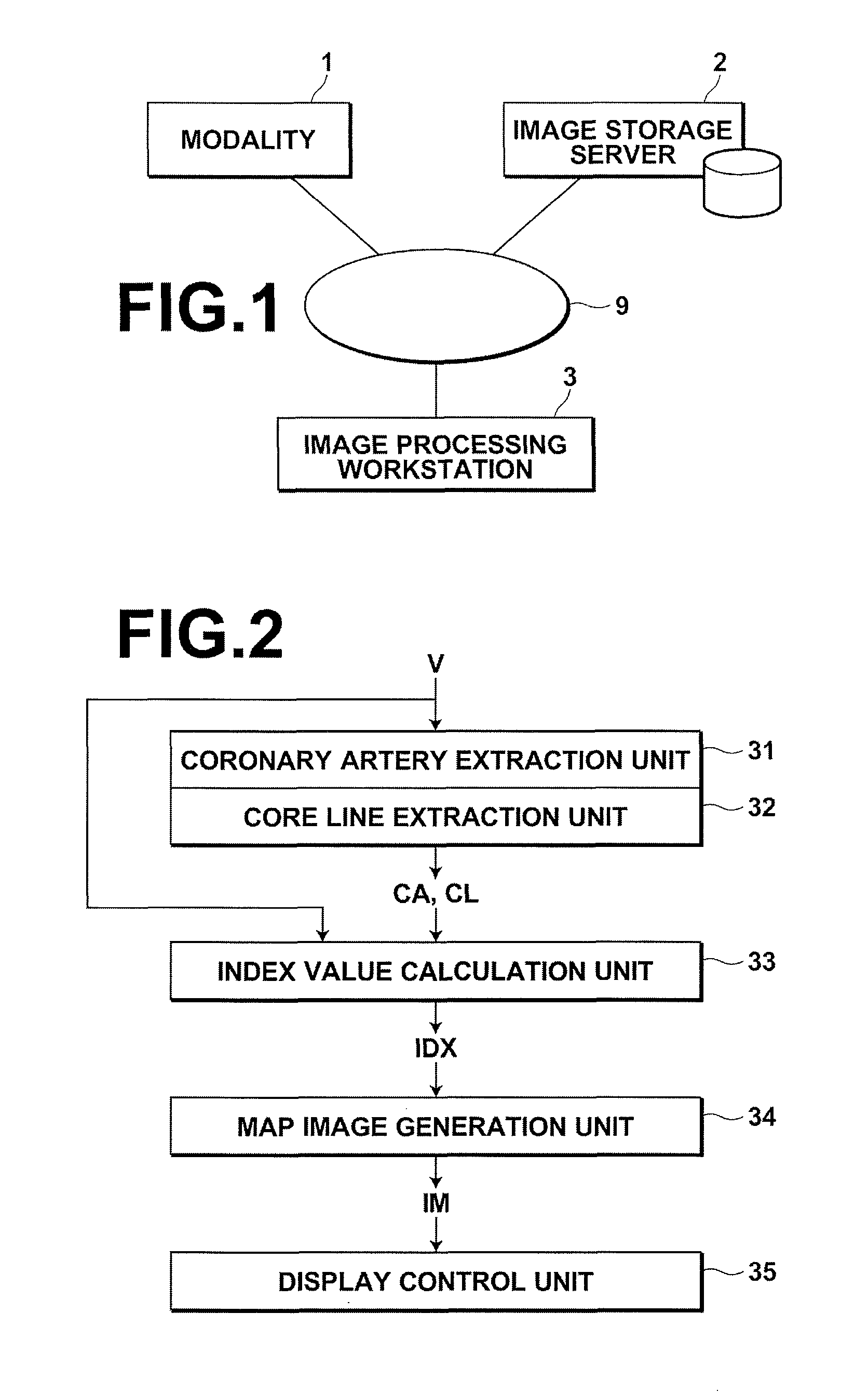
[0071]FIG. 2 is a block diagram of a part of image processing workstation 3 relevant to medical image processing of the present invention. As illustrated in FIG. 2, the medical image processing of the present embodiment is realized by coronary artery extraction unit 31, core line extraction unit 32, index value calculation unit 33, map image generation unit 34, and display control unit 35. The three-dimensional medical image V, coronary artery information CA, core line information CL, index value IDXm,n, and characteristic map image IM are data written into and read out from a predetermined memory area of image processing workstation 3 by each processing unit described above.

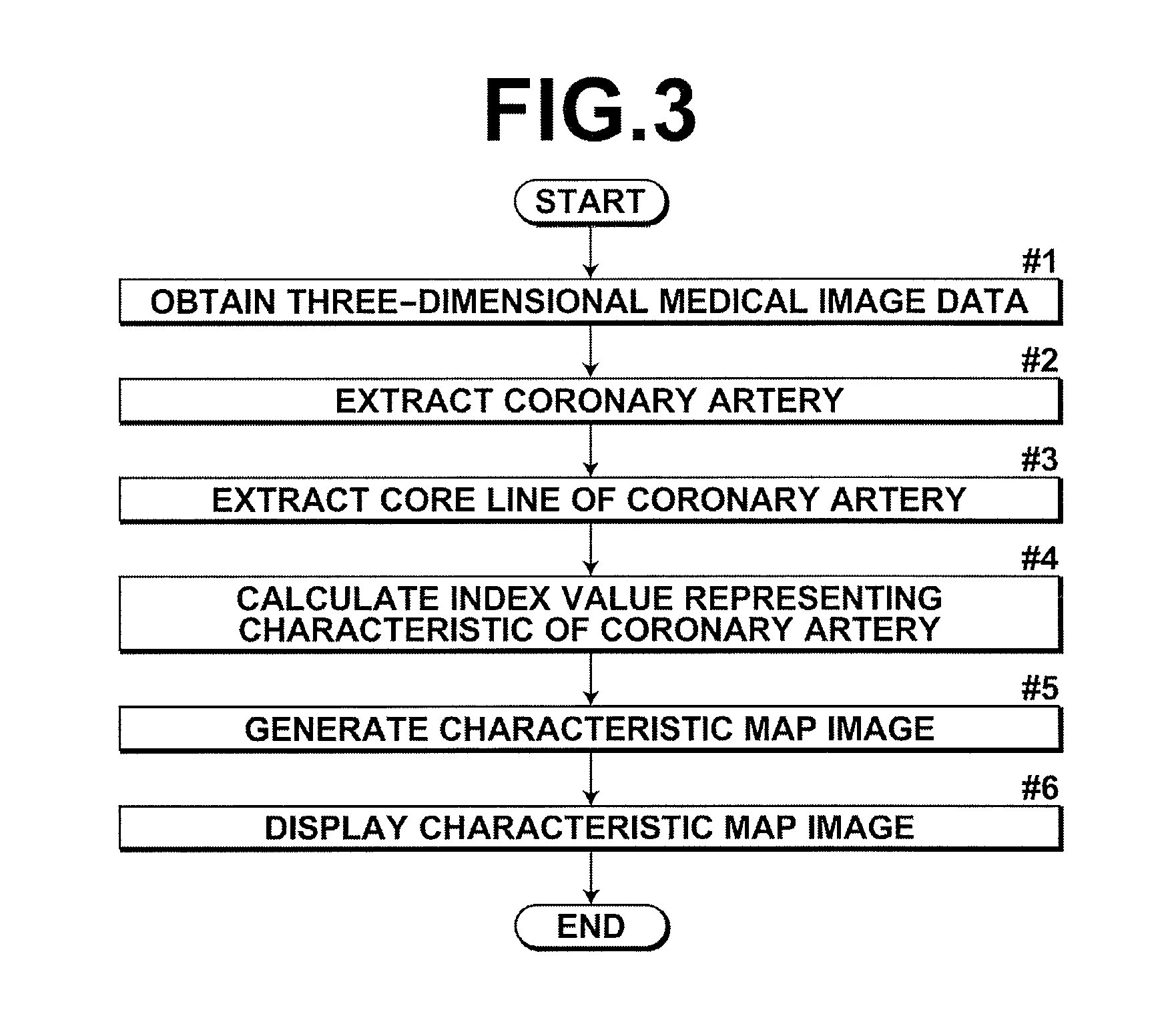
[0072]Next, processing performed by each unit described above will be described in detail along the flow of the medical image processing of a first embodiment of the present invention. FIG. 3 is a flowchart illustrating a flow of user operation, calculation processing, display processing, and the like under the ...

second embodiment

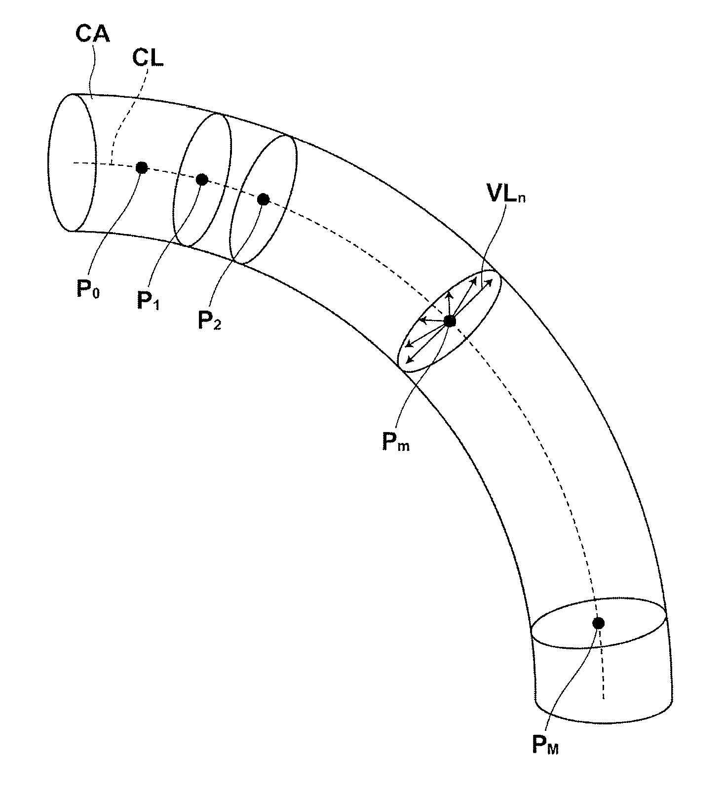
[0086]As described above, in the second embodiment, a characteristic map image IM by a rectangular coordinate system, as illustrated in FIG. 6B, 7B, or the like, is generated. This allows a characteristic (plaque distribution) of the coronary artery CA to be observed obviously with the vessel wall of the coronary artery CA being cut open and the interior of the coronary artery being represented in an exposing manner. Further, as the y axis represents the angle θn formed by each visual line VLn with respect to the visual line VL0 at each point Pm on the coronary artery CA, so that observation may be performed with the size of the coronary artery CA at each point Pm being normalized.

[0087]A third embodiment of the present invention is an embodiment that generates a characteristic map image in which two types of index values are mapped, and the block diagram and flowchart of the third embodiment are identical to those of the first embodiment.

[0088]In the present embodiment, index value...

third embodiment

[0089]As described above, in the present invention, distributions of the two types of index values can be obviously understood and the observation efficiency is further improved. For example, it is possible to understand as to whether or not a stenosis is developed at a position of a plaque only from the characteristic map image IM of the present embodiment.

[0090]In the present embodiment, characteristic map image IM is represented pseudo three-dimensionally, so that a position in the back side (rear side) with respect to the viewpoint of the characteristic map image IM is hard to observe. It is preferable, therefore, that the viewpoint and visual line with respect to the characteristic map image IM be settable and changeable. This allows the user to perform observation by rotating the characteristic map image IM.

[0091]A fourth embodiment of the present invention is an embodiment in which an orthogonal cross-section image with respect to the core line of a coronary artery and a char...


PUM


Abstract

A medical image processing apparatus in which an index value calculation unit calculates an index value representing a characteristic of a tubular structure extracted from a three-dimensional medical image in each direction of radial visual lines orthogonal to a core line of the tubular structure at each of a plurality of points on the core line with each point as each viewpoint and a map image generation unit generates a characteristic map image representing the characteristic inside of the tubular structure by mapping the index value calculated in each direction of the radial visual lines at each point on the core line to a coordinate plane defined by a first coordinate component representing a position in a direction of the core line and a second coordinate component representing a direction of each visual line.

Description

BACKGROUND OF THE INVENTION[0001]1. Field of the Invention[0002]The present invention relates to a medical image processing technology for representing a characteristic of a tubular structure in a three-dimensional medical image.[0003]2. Description of the Related Art[0004]Medical image analysis techniques have been advancing rapidly with a wide spread use of multi-detector row computed tomography in clinical practice. For example, in the field of cardiac medicine, it has become possible to image the entire heart in a shorter period of time and obtain an image without substantially any artifact due to cardiac motion. Consequently, in the image diagnosis of cardiac region, more detailed diagnosis of a stenosis portion of a coronary artery has become possible. In the field of coronary artery observation, a method for specifying a center line of an observation target coronary artery and examining orthogonal cross-sections orthogonal to the center line along the center line and a method...

Claims


Application Information

Patent Timeline
Patent Type & Authority Patents(United States)
IPC IPC(8): G06K9/00A61B5/05A61B6/00
CPCG06T7/0012G06T2200/04G06T2207/30101
Inventor MASUMOTO, JUN
Owner FUJIFILM CORP
Why Eureka
Try Eureka