
System with sub-nyquist signal acquisition and transmission and associated methods

a sub-nyquist signal and transmission system technology, applied in the field of data communication, can solve the problems of high sample rate converters, many samples with redundant information content about signals, and many samples with redundant information content, etc., and achieve the effect of reducing overall size, weight and power, and efficient processing of signals

Active Publication Date: 2013-09-17
HARRIS CORP
View PDF24 Cites 3 Cited by
  • Summary
  • Abstract
  • Description
  • Claims
  • Application Information

AI Technical Summary

Benefits of technology

This approach enables efficient signal processing with reduced power consumption, smaller size, and lower weight, while maintaining high resolution, and allows for error correction and authentication, making it suitable for battery-powered devices.

Problems solved by technology

However, there are penalties associated with implementing data compression.
One such penalty is that the original information bearing signal will likely be sampled above the Nyquist rate, and thus produce many samples with redundant information content about the signal.
High sample rate converters tend to require higher power and are often limited in resolution with respect to their lower sample rate counterparts.
This induces a system penalty of low resolution and high power.
In some cases it is difficult to even purchase or construct an ADC with the required sample rate given the Nyquist viewpoint of the signal.
Implementing compression prior to storage or transmission requires some type of computing resource, which in turn increases the power drawn by the sensor system.
The larger the oversampling factor in a Nyquist paradigm, the more severe these penalties become.
A disadvantage of this approach is that transform coding of the discrete signal before being compressively sampled requires additional processing, which in turn consumes power.
Additional power consumption may be undesirable, particularly for battery-powered systems.

Method used


Image

  • System with sub-nyquist signal acquisition and transmission and associated methods
  • System with sub-nyquist signal acquisition and transmission and associated methods
  • System with sub-nyquist signal acquisition and transmission and associated methods

Examples


Embodiment Construction

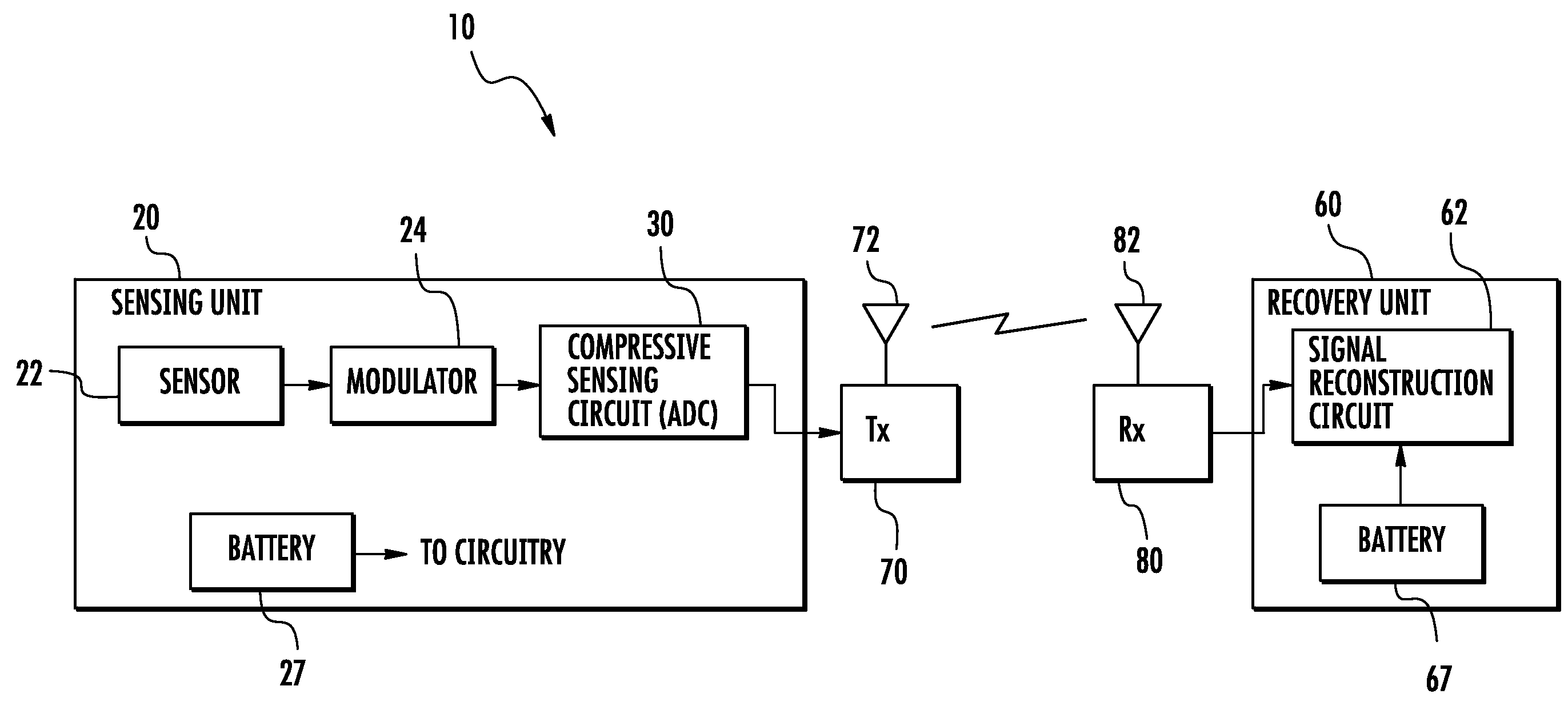
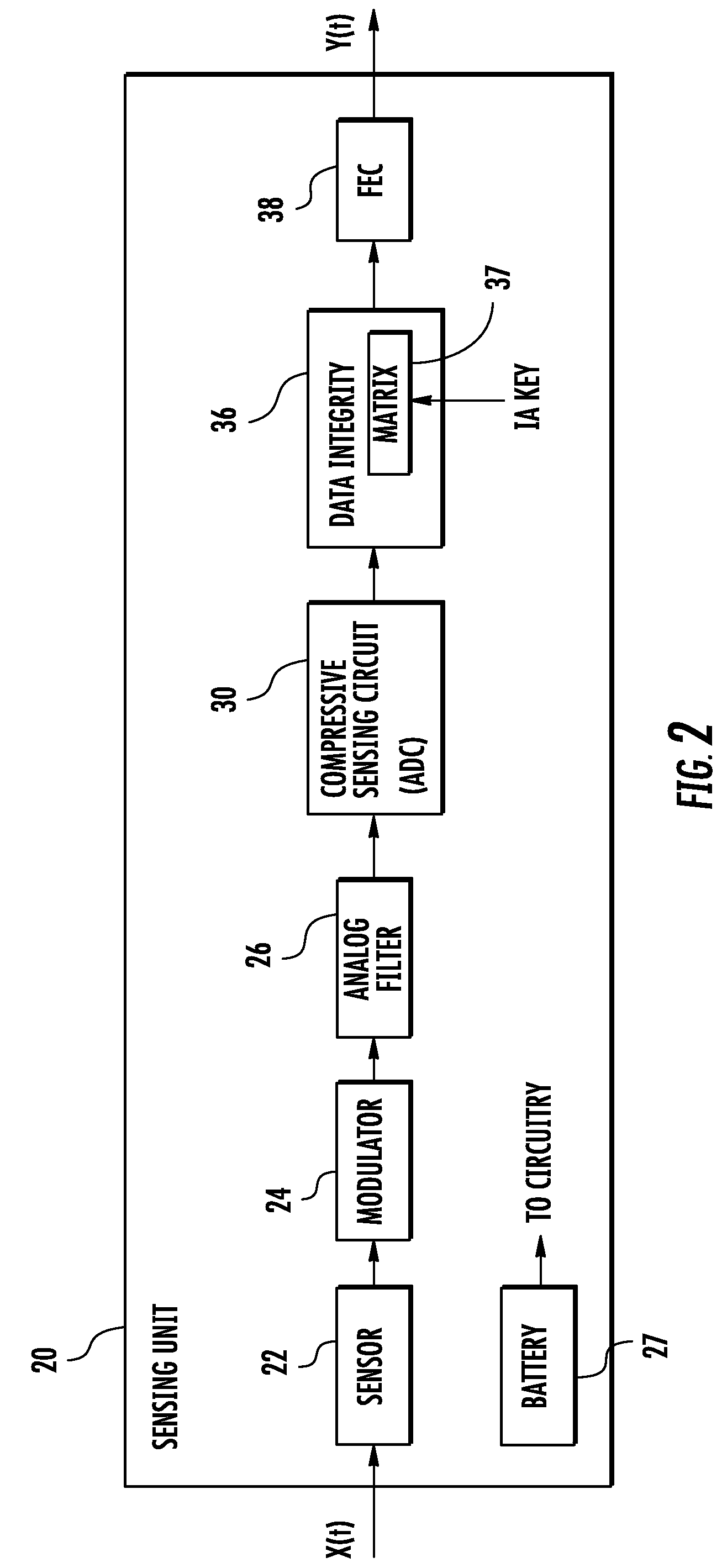
[0022]The present invention will now be described more fully hereinafter with reference to the accompanying drawings, in which preferred embodiments of the invention are shown. This invention may, however, be embodied in many different forms and should not be construed as limited to the embodiments set forth herein. Rather, these embodiments are provided so that this disclosure will be thorough and complete, and will fully convey the scope of the invention to those skilled in the art.

[0023]Compressive sensing enables a high resolution capture of physical signals from relatively few measurements, which may be well below the number expected from the requirements of the Shannon / Nyquist sampling theorem. Compressive sensing makes use of a sparse representation for the received signal, and then measurements are used to extract the maximum amount of information from the sparse representation for the received signal using a minimum amount of measurements.

[0024]Compressive sensing as discus...


PUM


Abstract

A sensing and recovery system includes a sensing unit and a recovery unit coupled together. The sensing unit includes a sensor to generate a bandlimited continuous time analog signal, and a modulator coupled to the sensor to generate a modulated analog signal based upon modulation of the bandlimited continuous time analog signal at a modulating rate at least equal to a Nyquist rate for the bandlimited continuous time analog signal. A compressive sensing circuit is coupled to the modulator to generate a compressed sensed signal based upon conversion of the modulated analog signal at a sampling rate less than the Nyquist rate. The recovery unit recovers the bandlimited continuous time analog signal from the compressed sensed signal.

Description

FIELD OF THE INVENTION[0001]The present invention relates to the field of data communications, and more particularly, to a sensing and recovery system and method using compressive sensing.BACKGROUND OF THE INVENTION[0002]In digital signal analysis, a signal is typically reconstructed from discrete measurements. Typical approaches to sampling signals or images follow Shannon's theorem wherein a sufficient sampling rate is at least twice the bandwidth (i.e., a lowpass or bandpass bandwidth depending on the signal type) present in the signal. This minimal sampling rate is known as the Nyquist rate or frequency.[0003]This principle underlies nearly all signal acquisition protocols used in consumer audio and video electronics, medical imaging devices, radio receivers, etc. In reference to data conversions, for example, a standard analog-to-digital converter (ADC) implements the quantized Shannon representation in that the signal is uniformly sampled at or above the Nyquist rate.[0004]Eve...

Claims


Application Information

Patent Timeline
Patent Type & Authority Patents(United States)
IPC IPC(8): H04B5/00
CPCH04B1/0025H04L25/4904
Inventor BEADLE, EDWARD R.ZAHM, CHARLES
Owner HARRIS CORP
Learn More