
Stretchable high-loft flat-tube structure from continuous filaments
a flat-tube structure, high-loft technology, applied in the direction of upholstery, packaging, synthetic resin layered products, etc., can solve the problems of high loft, high tensile strength, and oscillation of chutes, and achieve high loft, good stretch recovery properties, and dimensional stability. good
- Summary
- Abstract
- Description
- Claims
- Application Information
AI Technical Summary
Benefits of technology
Problems solved by technology
Method used
Image

Examples
example 1
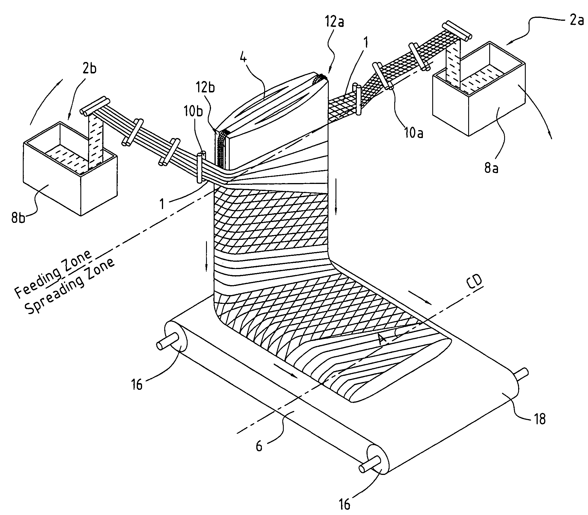
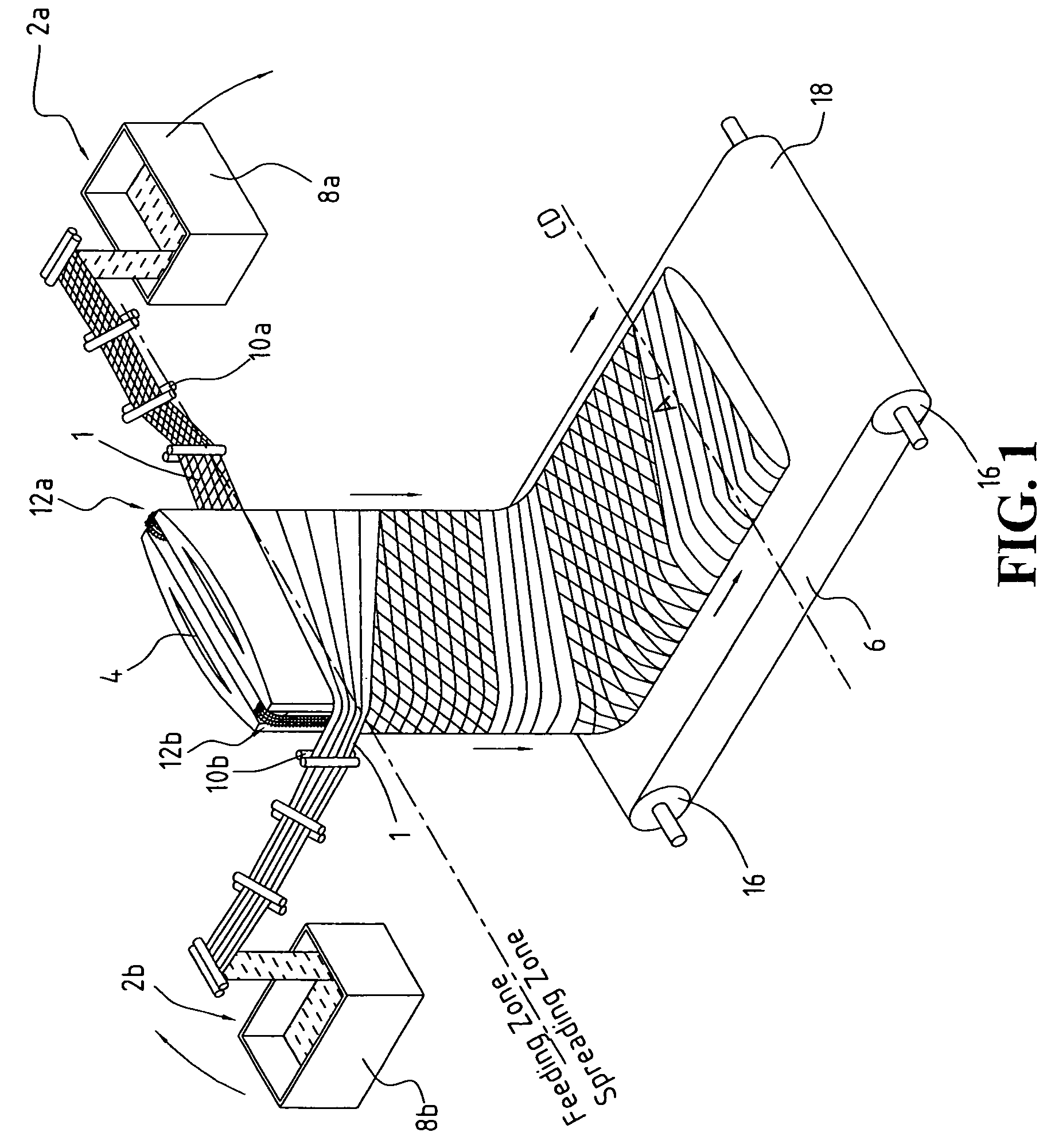
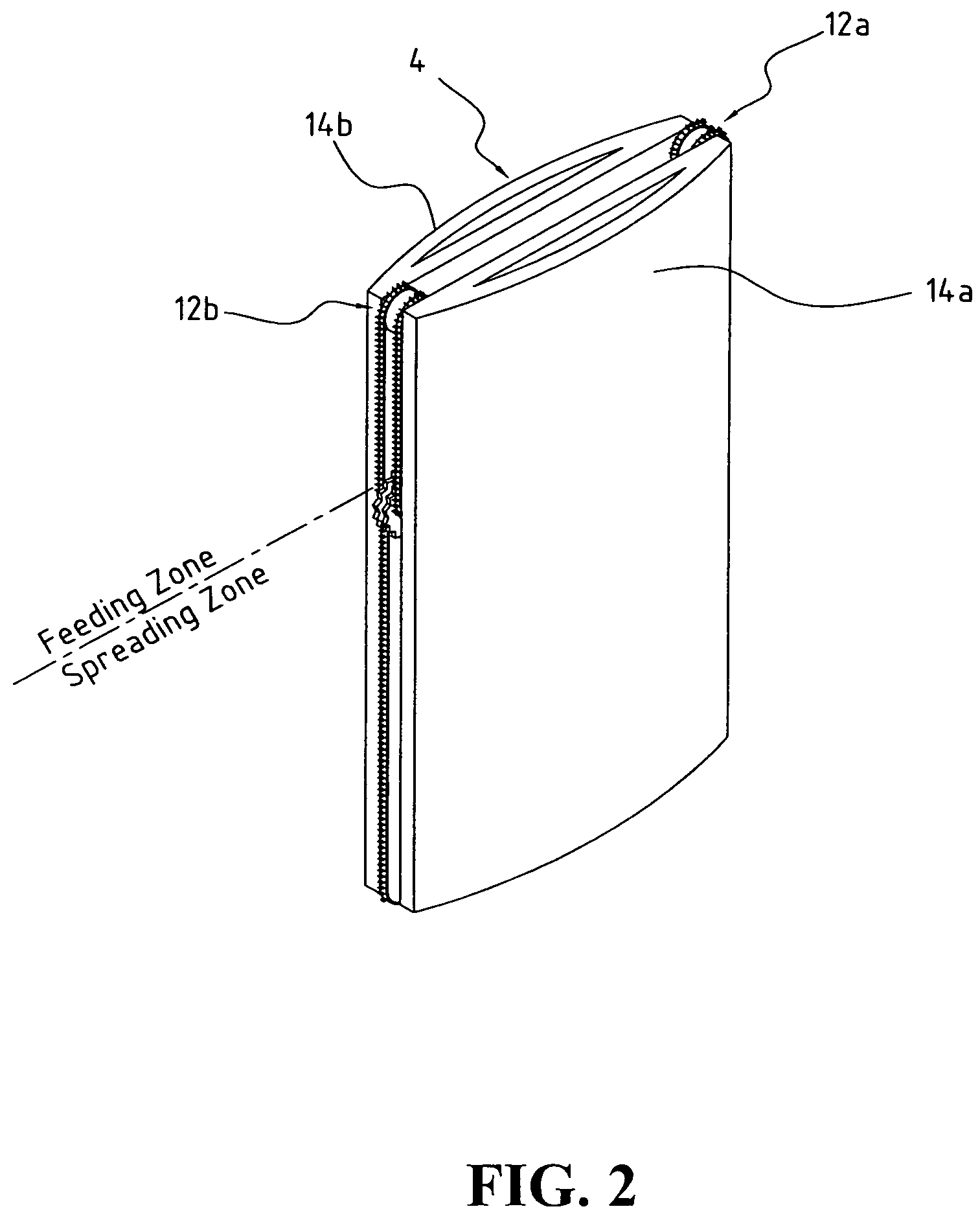
[0078]Referring to FIG. 1, a tow 1 of crimped continuous filaments with 100,000 filaments and total denier of 600,000 having a width of 0.125 meter is fed from container 8a through a series of feeding and spreading rolls 10a which widen it to a 0.25-meter tow band, then wrap it clockwise around a 2-meter-wide batt-forming device 4 and engage it with conveyor 2a in the feeding zone at a speed equal to 0.25 meter per second. The feeding zone conveyor surface speed is about 0.03125 meter per second, which is about ⅛ of the feeding speed of the tow 1 wrapping around the batt-forming device 4. The tow 1 is spread by conveyor 12a in the spreading zone at a surface speed of 0.25 meter per second, resulting in a spread ratio of 8, which is equal to the conveyor surface speed in the spreading zone divided by the conveyor surface speed in the feeding zone. By the time the tow band travels 2 meters to reach and engage with conveyor 12b in the feeding zone, the first portion of the tow 1 at 12a...
example 2
[0079]Referring to FIG. 1, a tow 1 of crimped continuous filaments with 100,000 filaments and total denier of 600,000 as in Example 1 is fed to the batt-forming device 4 at the same speed as in Example 1. A second tow 1 is also identical to that of Example 1 and is fed to the batt-forming device 4 as described in Example 1. The only exception is that the spread ratio is 4 instead of 8 as in Example 1. The resulting spread flat-tube structure has filament orientation of about a 27-degree angle relative to the CD direction. The flat-tube structure has a cross-lapped angle between layers of about 54 degrees.
example 3
[0080]Referring to FIG. 1, a tow 1 of crimped continuous filaments with 100,000 filaments and total denier of 600,000 as in Example 1 is fed to the batt-forming device at speed as in Example 1. A second tow 1 identical to that of Example 1 is fed to batt-forming device 4 as described in Example 1. The only exception is that the spread ratio is 12 instead of 8 as in Example 1. The resulting spread flat-tube structure has a filament orientation of about a 56-degree angle relative to the CD direction, and a cross-lapped angle between layers of about 112 degrees.
PUM
| Property | Measurement | Unit |
|---|---|---|
| width | aaaaa | aaaaa |
| angle | aaaaa | aaaaa |
| angle | aaaaa | aaaaa |
Abstract
Description
Claims
Application Information