
Coding/decoding of digital audio signals

a digital audio and signal technology, applied in the field of processing acoustic data, can solve the problems of not all received by the decoder, and the problem of continuity and homogeneity of spectra between sub-bands

Active Publication Date: 2013-09-24
FRANCE TELECOM SA
View PDF13 Cites 21 Cited by
  • Summary
  • Abstract
  • Description
  • Claims
  • Application Information

AI Technical Summary

Benefits of technology

The present invention improves the quality of audio signals by allocating bits to sub-bands based on their importance in the perceptual sense. This helps to optimize the distribution of bits and improve overall audio quality. Additionally, the invention allows for the weighting of the entire spectral band, which is beneficial for certain applications such as G.729.1 coding. The technical effect of the invention is improved audio quality through perceptual weighting.

Problems solved by technology

It can occur however that they are not all received by the decoder.
If it is desired to apply perceptual weighting in the frequency domain, the problem then posed is the continuity and homogeneity of the spectra between sub-bands.

Method used


Image

  • Coding/decoding of digital audio signals
  • Coding/decoding of digital audio signals
  • Coding/decoding of digital audio signals

Examples


first embodiment

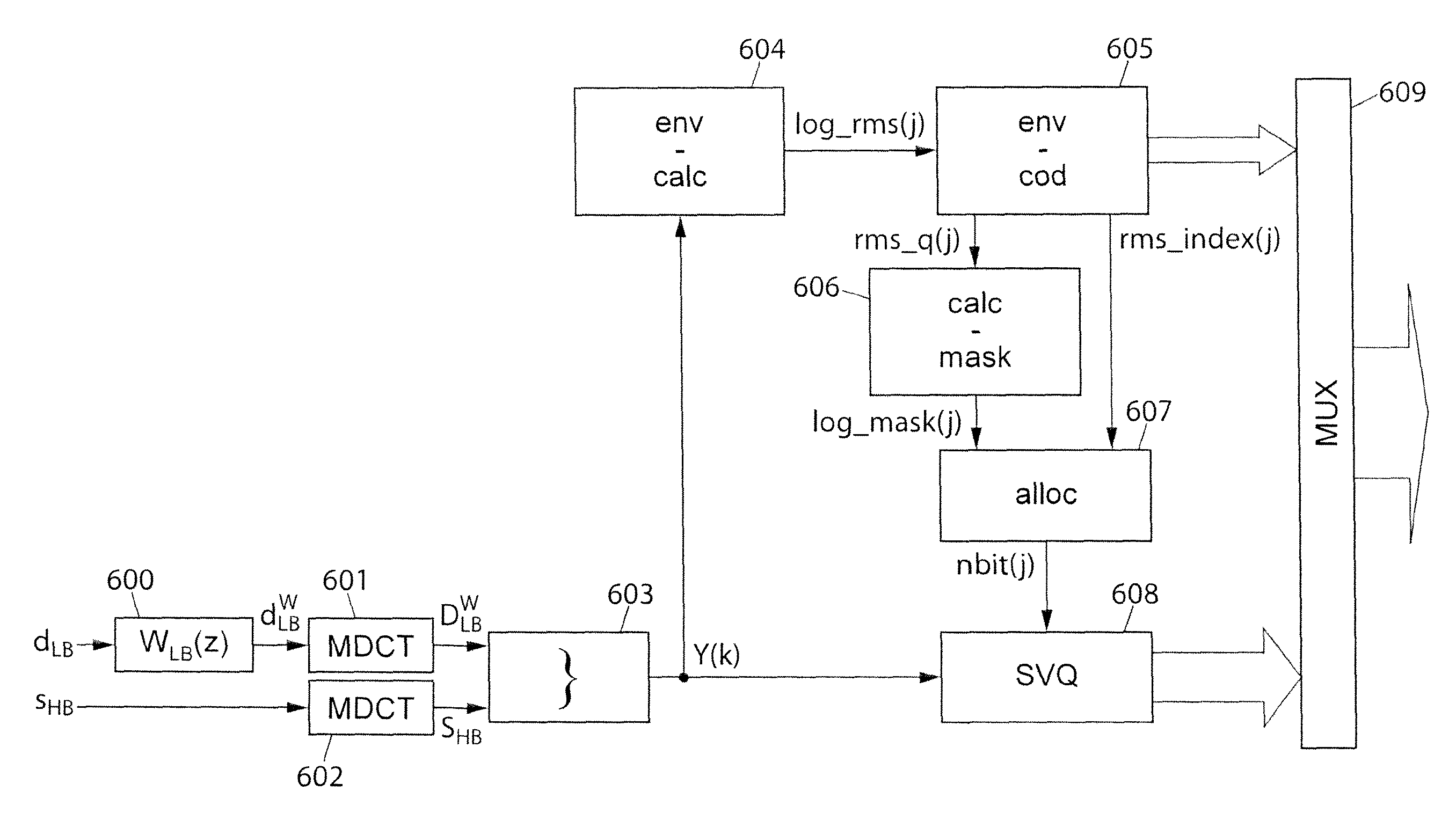
[0146]In a first embodiment described hereafter with reference to FIG. 6, the modified TDAC coder is identical to that in FIG. 3, with the exception that the bit allocation following the root mean square deviation (block 306) is henceforth replaced by a masking curve computation and a modified bit allocation (blocks 606 and 607), the invention being included within the framework of the masking curve computation (block 606) and its use in the allocation of bits (block 607).

[0147]Similarly, the modified TDAC decoder is shown in FIG. 7 in this first embodiment. This decoder is identical to that in FIG. 4, with the exception that the bit allocation following the root mean square deviation (block 402) is replaced by a masking curve computation and a modified bit allocation (blocks 702 and 703). In a symmetrical fashion to the modified TDAC coder, the invention relates to blocks 702 and 703.

[0148]Blocks 606 and 702 carry out an identical operation on the basis of the values rms_index(j), ...

second embodiment

[0198]This second embodiment can prove particularly advantageous, in particular in an implementation according to standard 3GPP-AMR-WB+ which is presented as the preferred environment of the above-mentioned document by Ragot et al.

[0199]In a variant of this second embodiment, as shown in FIGS. 9B and 10B (the same references in FIGS. 9A and 9B, and 10A and 10B, denote the same elements), the coded information remains the energy envelope (rather than the masking threshold itself such as in FIGS. 9A and 10A).

[0200]On coding, the masking threshold is computed and normalized (block 906b in FIG. 9B) on the basis of the coded spectral envelope (block 905b). On decoding, the masking threshold is computed and normalized (block 1011b in FIG. 10B) on the basis of the decoded spectral envelope (block 1001b), the decoding of the envelope making it possible to carry out a level adjustment (block 1010b in FIG. 10B) on the basis of the quantized values rms_q(j).

[0201]Thus, in case of zero decoded ...


PUM


Abstract

The invention relates to the coding / decoding of a signal into several sub-bands, in which at least a first and a second sub-bands which are adjacent are transform coded (601, 602). In particular, in order to apply a perceptual weighting, in the transformed domain, to at least the second sub-band, the method comprises:—determining at least one frequency masking threshold (606) to be applied on the second sub-band; and normalizing said masking threshold in order to provide a spectral continuity between the above-mentioned first and second sub-bands. An advantageous application of the invention involves a perceptual weighting of the high-frequency band in the TDAC transform coding of a hierarchical encoder according to standard G.729.1.

Description

CROSS-REFERENCE TO RELATED APPLICATIONS[0001]This application is the U.S. national phase of the International Patent Application No. PCT / FR2008 / 050150 filed Jan. 30, 2008, which claims the benefit of French Application No. 07 00747 filed Feb. 2, 2007, the entire content of which is incorporated herein by reference.BACKGROUND OF THE INVENTION[0002]The present invention relates to processing acoustic data.[0003]This processing is suitable in particular for the transmission and / or storage of digital signals such as audio-frequency signals (speech, music, or other).[0004]Various techniques exist for coding an audio-frequency signal in digital form. The most common techniques are:[0005]waveform encoding methods such as pulse code modulation (PCM) and adaptive differential pulse code modulation (ADPCM).[0006]analysis-by-synthesis parametric coding methods such as code excited linear prediction (CELP) coding and[0007]sub-band perceptual coding methods or transform coding.[0008]These techni...

Claims


Application Information

Patent Timeline
Patent Type & Authority Patents(United States)
IPC IPC(8): G10L19/04G06F40/00G10L19/00G10L19/002G10L19/02G10L19/038G10L19/12G10L19/24
CPCG10L19/0204G10L19/002G10L19/24G10L19/038G10L19/0212G10L19/12G10L19/02
Inventor RAGOT, STEPHANEGUILLAUME, CYRIL
Owner FRANCE TELECOM SA
Learn More