Construction machine

a construction machine and construction technology, applied in the direction of electric propulsion mounting, machines/engines, jet propulsion mounting, etc., can solve the problems of deterioration in the cooling efficiency of fluids by heat exchangers, aggravated workability in maintenance operations, and inability to secure a space for operators, so as to improve the cooling efficiency

Active Publication Date: 2013-10-08
NIHON KENKI CO LTD
View PDF26 Cites 19 Cited by
  • Summary
  • Abstract
  • Description
  • Claims
  • Application Information

AI Technical Summary

Benefits of technology

[0010]In view of the above-described problems with the prior art, it is an object of the present invention to provide a construction machine in which, even in a case where the inlet port and the exhaust port are provided in a small heat exchanger cover, the cooling air which is exhausted from the exhaust port can be exhausted to a location distant from the inlet port so as to prevent the re-sucking of warm air, thereby making it possible to improve the efficiency of cooling by the heat exchanger.
[0011]Another object of the present invention is to provide a construction machine in which the cooling air flowing inside the exterior cover by the cooling fan is guided toward the exhaust port provided in the engine cover, to thereby allow the cooling air to be efficiently circulated inside of the exterior cover.

Problems solved by technology

However, in the case where the configuration provided is such that a large opening is provided in the top plate and this opening is covered by the engine cover, with a small-size hydraulic excavator in which the upper revolving structure is formed compactly, there is a problem in that it is impossible to secure a space for the operator to get on the top plate, so that the workability in the maintenance operation is aggravated.
For this reason, there is a problem in that a recirculation can occur in which warmed air discharged from the exhaust port is sucked again from the inlet port, causing deterioration in the cooling efficiency of fluids by the heat exchanger.

Method used


Image

  • Construction machine
  • Construction machine
  • Construction machine

Examples


Embodiment Construction

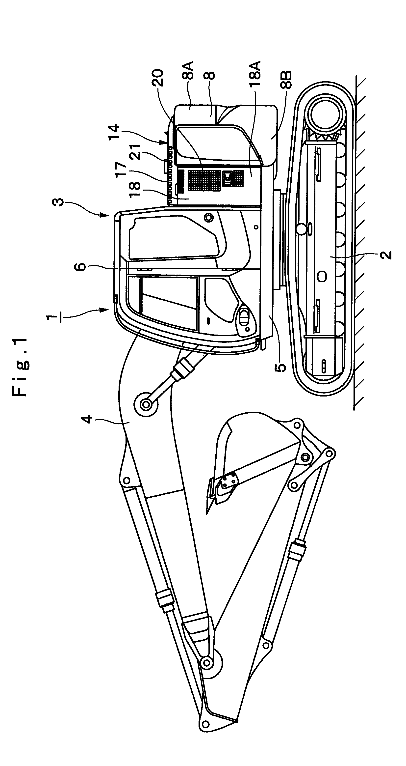
[0068]Hereafter, with reference to FIGS. 1 to 9, a detailed description will be given by citing a crawler type hydraulic excavator as an example of a construction machine in accordance with an embodiment of the present invention.

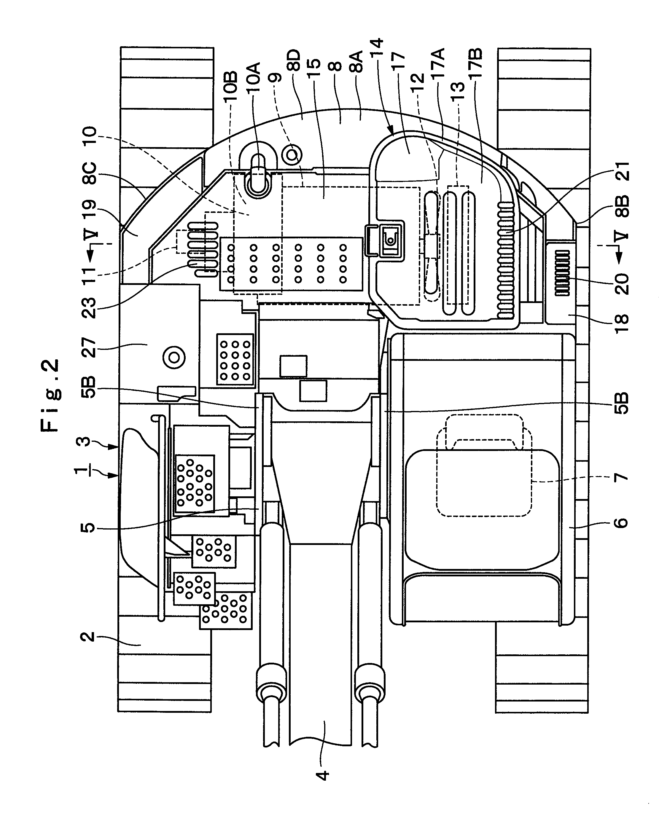
[0069]In FIG. 1, designated at 1 is a crawler type hydraulic excavator as a construction machine, and the hydraulic excavator 1 is largely constituted by an automotive lower traveling structure 2, an upper revolving structure 3 which is swingably mounted on the lower traveling structure 2 and constitutes a vehicle body together with the lower traveling structure 2, and a working mechanism 4 liftably mounted on the front side of the upper revolving structure 3 to perform the operation of such as excavating earth and sand.

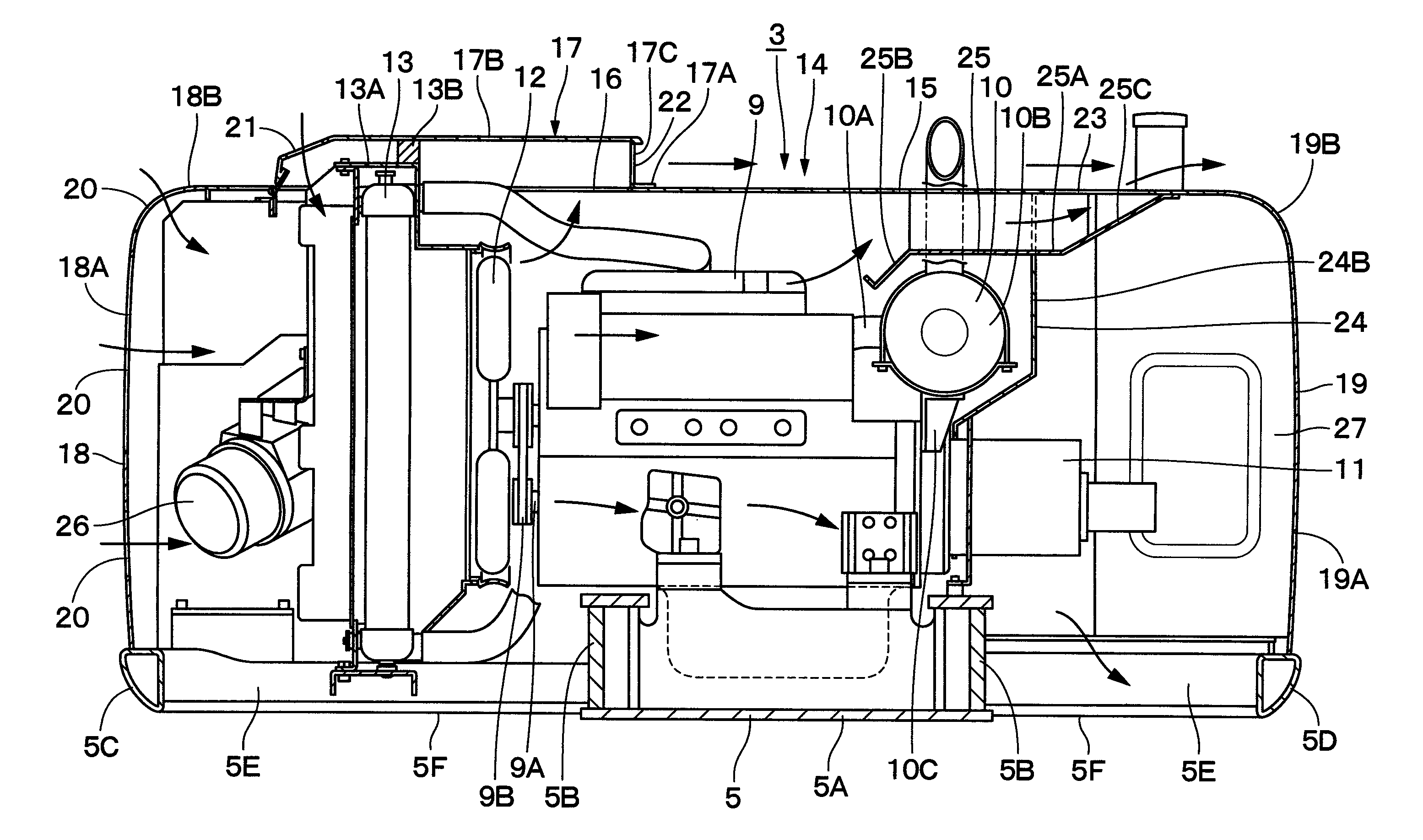
[0070]Indicated at 5 is a revolving frame serving as a vehicle frame constituting a part of the upper revolving structure 3, and the revolving frame 5 is formed as a support structure. Further, as shown in FIG. 5, the revolving frame 5 is lar...


PUM


Abstract

In a heat exchanger cover (17) covering upper sides of heat exchanger (13), an inlet port (21) is provided on a left side which is an upstream side of cooling air, and one exhaust port (22) for exhausting the cooling air which has passed through the heat exchanger (13) is provided on a right side opposite to this inlet port (21). An engine cover (15) is provided with another exhaust port (23) at a position opposing the one exhaust port (22) in a left-right direction. The cooling air which has passed through the heat exchanger (13) can be exhausted horizontally from the exhaust port (22) provided in the heat exchanger cover (17) toward the exhaust port (23) provided in the engine cover (15).

Description

TECHNICAL FIELD[0001]The present invention relates to a construction machine such as a hydraulic excavator, a hydraulic crane, a wheel loader, or the like, and more particularly to a construction machine having an exterior cover which covers mounted equipment including an engine, or the like.BACKGROUND ART[0002]Generally, a hydraulic excavator as a construction machine is largely constituted by an automotive lower traveling structure, an upper revolving structure which is swingably mounted on the lower traveling structure, and a working mechanism liftably mounted on the front side of the upper revolving structure.[0003]The upper revolving structure is largely constituted by a revolving frame serving as a support structure, an engine which is mounted on the rear side of the revolving frame and drives a hydraulic pump, a cooling fan which is rotatively driven by the engine, heat exchanger such as a radiator and an oil cooler which are provided in face-to-face relation to the cooling f...

Claims


Application Information

Patent Timeline
Patent Type & Authority Patents(United States)
IPC IPC(8): B60K11/06
CPCB60K11/04B60K11/08E02F9/00E02F9/0891B60Y2200/41F01P11/10
Inventor ISAKA, WATARUTANAKA, NOZOMU
Owner NIHON KENKI CO LTD
Why Eureka
Try Eureka