Mandibular manipulator and related methods

a manipulator and mandibular technology, applied in the field of medical and dental equipment, can solve the problems of inability to accurately analyze a patient in real time, error method, lack of precision and repeatability, etc., to prevent breathing difficulties, improve diagnostic accuracy, and open the throat

Inactive Publication Date: 2013-10-08
KOSMO TECH
View PDF91 Cites 13 Cited by
  • Summary
  • Abstract
  • Description
  • Claims
  • Application Information

AI Technical Summary

Benefits of technology

[0008]The mechanical connection between the mandible and maxilla engagement allows for a means of two self-retaining sliding incisor pulls that move perpendicular to one another and three rotating members to actuate the pulls. The incisor pulls have a self-retaining shape and also have a small protrusion at one end so as to prevent their leaving the guide slots once a device according to the invention is assembled for use. The mechanical connection allows for motion of the incisor sliding pulls in both an anterior / posterior direction and a vertical direction and a third mechanical connection is provided to allow sagittal or right and left relative motion of the incisor pulls. A locking means is provided for the anterior / posterior motion and the vertical motion to allow the ideal position to be held. The sagittal position is held by means of its thread / nut mechanism utilized for its positioning.
[0011]Graduated scales or gradation markings or indicators are marked in the connecting frame of the instrument to accurately quantify the movement in both the anteroposterior, vertical axes as well as the sagittal movement. In another refined embodiment, the instrument allows for electronic feedback of the positions to be recorded by data logger or other computer recording, thus allowing for an automatic record of the mandible position.
[0014]In yet another embodiment, the position of the mandible relative to the maxilla can be precisely measured or positioned while using electrodiagnostic equipment or radiology to realize the necessary location of the mandible, for creating a remedy for patients suffering from TMJ.
[0015]One use of the device is in the application of an acoustic oral pharyngometer instrument to measure the area and volume of the throat opening of a patient as he or she breathes. The simple motion of moving the lower mandible either anteroposterior and up and down, can help open the throat and ease breathing. The outcome of the procedure is to either create a dental appliance to use while the patient sleeps or for referral to another medical professional for further analysis of the patient's throat. Typically, a dental appliance is constructed from the resulting oral pharyngometer procedure and this is used to hold the mandible in a set position as the patient sleeps to prevent breathing difficulties. This invention allows the oral pharyngometer procedure to be performed in real time without having to sequentially remove the adjusting instrument.
[0018]In yet another embodiment, the position of the mandible relative to the maxilla can be precisely measured or positioned while using electrodiagnostic equipment or radiology to realize the necessary location of the mandible, for creating a remedy for patients suffering from TMJ.

Problems solved by technology

Several problems can occur with the current method of achieving desired mandibular position because the patient is instructed to, e.g., position their mandible as the dental / medical procedure is performed.
Present methods lack the precision and repeatability needed to analyze a patient in real time with any diagnostic instrument or during other dental procedures requiring mandibular manipulation.
This trial-and-error method not only increases the diagnosis time, but prevents an accurate means of noting where the relative position of the mandible lies in relation to the maxilla.
And, in some cases, the patient becomes dissatisfied with the overall lack of good results and gives up.

Method used


Image

  • Mandibular manipulator and related methods
  • Mandibular manipulator and related methods
  • Mandibular manipulator and related methods

Examples


Embodiment Construction

[0052]The following terminology is used herein:

[0053]Dental Articulator: Mechanical instruments that simulate the temporomandibular joints and jaws to which maxillary and mandibular casts are attached. The entire assembly attempts to reproduce the movements of the mandible and the various tooth-to-tooth relationships that accompany those movements.

[0054]Maxilla: anatomy: of a pair of bones of the human skull fusing in the mid line and forming the upper jaw.

[0055]Dental: The irregularly shaped bone forming half of the upper jaw. The upper jaw is made up of the two maxillae.

[0056]Incisal edges of the lower to upper central incisor teeth.

[0057]Anteroposterior: Anatomical term referring to an axis and for the purpose of this application defines an axis from front to back of the mouth.

[0058]Sagittal: A vertical plane passing through the standing body from front to back.

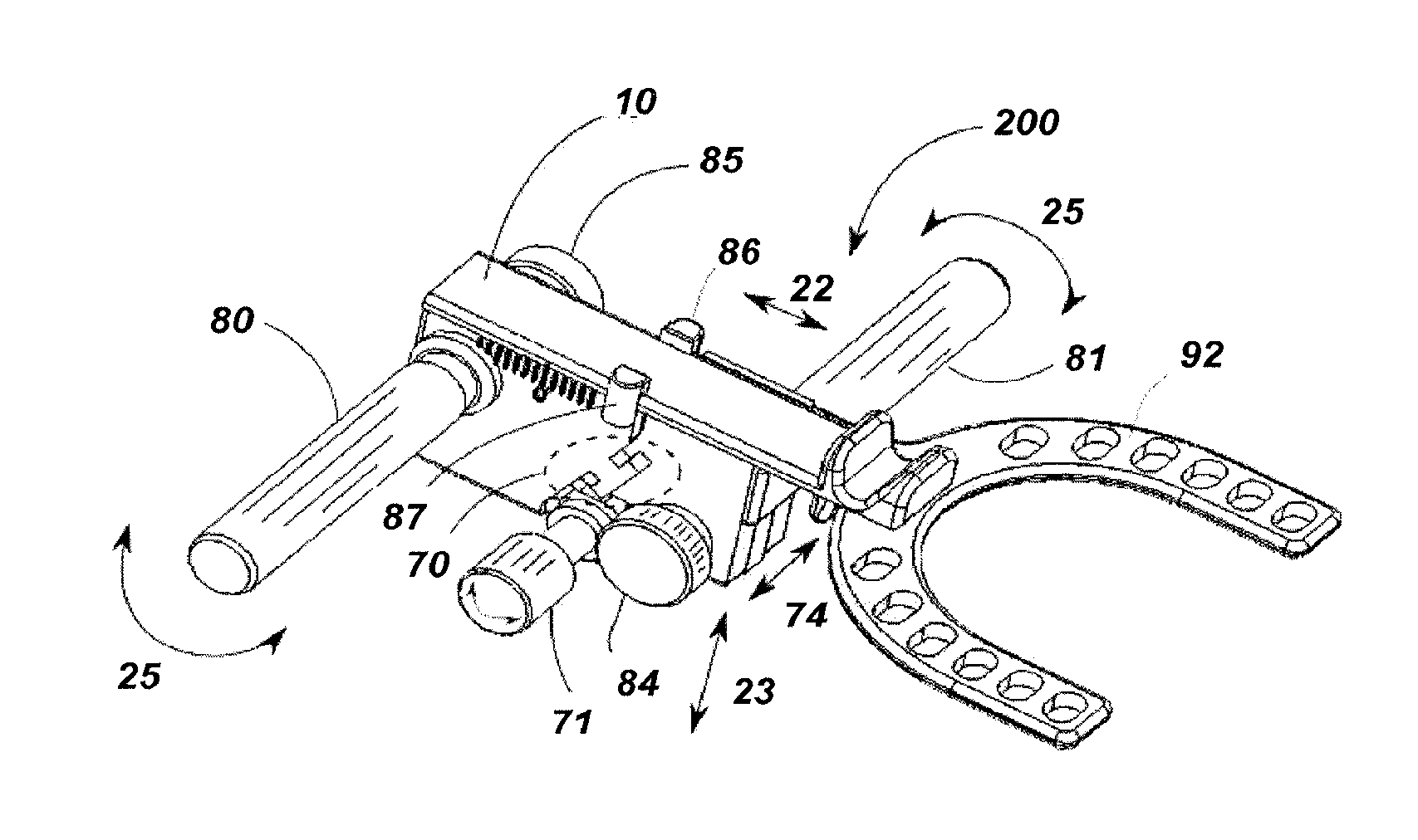
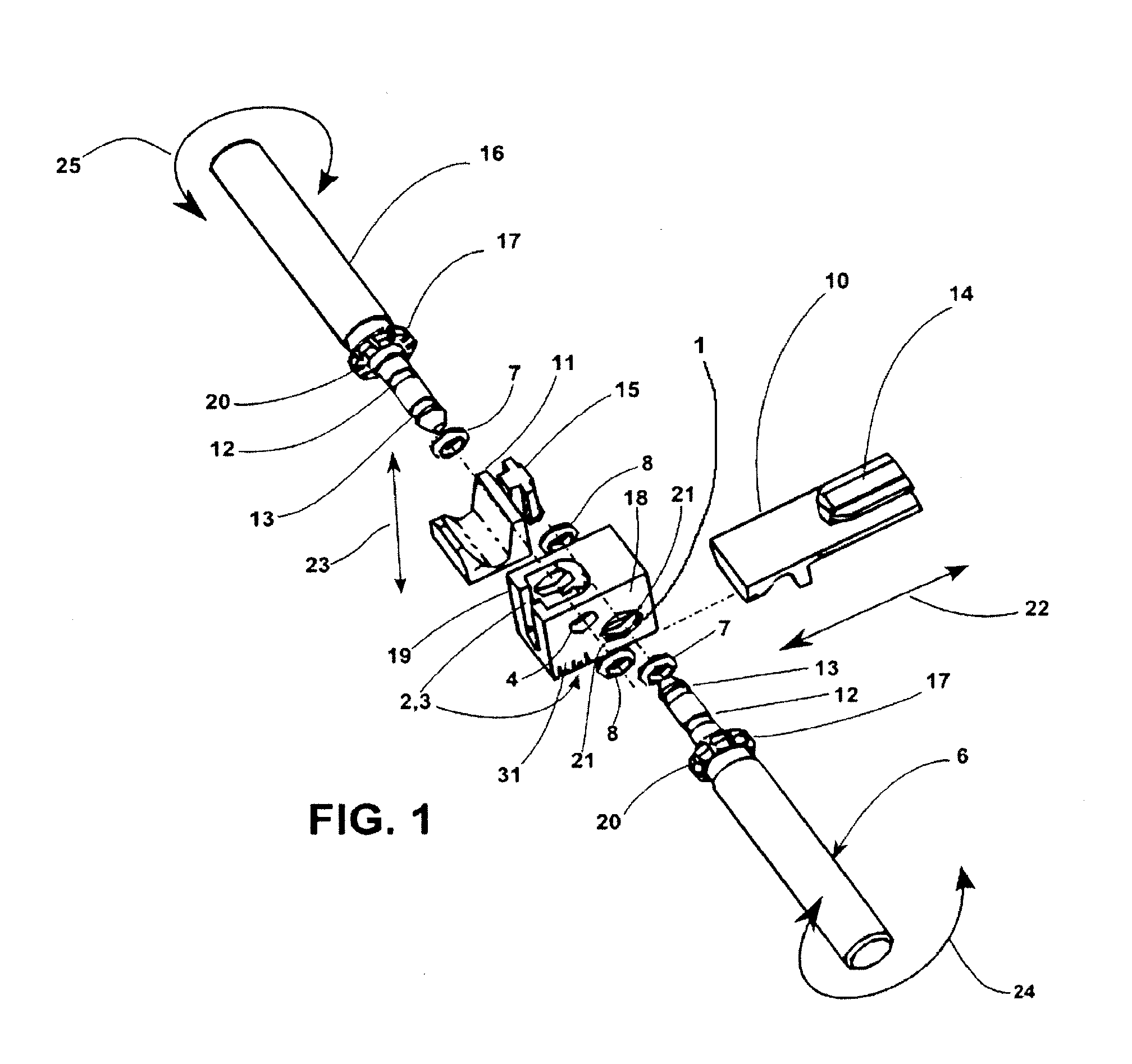
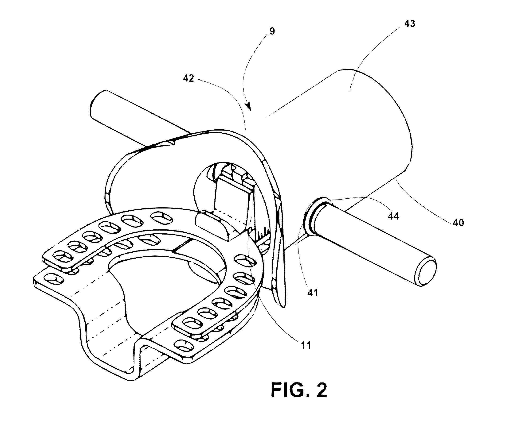
[0059]With reference now to FIGS. 1, 2, and 3, arrow 9 shows the overall mandibular manipulator as a self-contained unit...


PUM

PropertyMeasurementUnit
sagittal movementaaaaaaaaaa
mechanicalaaaaaaaaaa
self-retaining shapeaaaaaaaaaa

Abstract

Described is a mandibular manipulator instrument as a standalone tool or with associated mouthpiece that includes two interlocking laterally sliding frames including a movable upper and a lower incisor pull, shaped for receiving a patient's central incisor teeth and a pair of pinion shafts for driving the upper and lower incisor pulls. A screw thread is used to provide a precise lateral motion for the sagittal measurement. The mouthpiece is constructed of resilient rubber. The manipulator is positioned and held in the resilient rubber mouthpiece by the two pinions protruding through acoustically tight apertures respective to each pinion's position. The manipulator can be used for other applications in an embodiment without the mouthpiece and / or in combination with a bite registration shape that is part of the manipulator frame.

Description

CROSS-REFERENCE TO RELATED APPLICATIONS[0001]This application is a continuation-in-part of co-pending U.S. patent application Ser. No. 13 / 130,517, filed May 20, 2011, U.S. Pat. No. 8,226,407 (Jul. 24, 2012), which application is a national phase entry under 35 U.S.C. §371 of International Patent Application PCT / US2010 / 001839, filed Jun. 24, 2010, published in English as International Patent Publication WO 2011 / 005299 on Jan. 13, 2011, which claims the benefit under Article 8 of the Patent Cooperation Treaty and under 35 U.S.C. §119(e) to U.S. Patent Application Ser. No. 61 / 269,344, filed on Jun. 24, 2009, the disclosure of each of which is hereby incorporated herein in its entirety by this reference. This application is also a continuation of International Patent Application PCT / US2012 / 022089, filed Jan. 20, 2012, which claims the benefit under Article 8 of the Patent Cooperation Treaty and under 35 U.S.C. §119(e) to U.S. Patent Application Ser. No. 61 / 461,657, filed Jan. 21, 2011, ...

Claims


Application Information

Patent Timeline
Patent Type & Authority Patents(United States)
IPC IPC(8): A61C5/00
CPCA61B5/1076A61B5/1121A61B5/4552Y10T29/49826
Inventor HANEWINKEL, WILLIAM H.GLEESON, MICHAEL B.
Owner KOSMO TECH
Why Eureka
Try Eureka