Internal combustion engine with exhaust gas turbocharger

a technology of exhaust gas and turbocharger, which is applied in the direction of engine components, hot gas positive displacement engine plants, mechanical apparatus, etc., can solve the problems of delayed response of the turbocharger and a certain amount of time for the torque to build, and achieve the effect of improving the utilization of the energy of the exhaust gas

Active Publication Date: 2013-10-15
DR ING H C F PORSCHE AG
View PDF16 Cites 14 Cited by
  • Summary
  • Abstract
  • Description
  • Claims
  • Application Information

AI Technical Summary

Benefits of technology

[0004]The invention is therefore related to the goal of designing an internal combustion engine of the type indicated above in a way which improves the utilization of the energy of the exhaust gas. This is achieved according to aspects of the invention by an internal combustion engine.
[0006]The inventive circuit makes it possible to divert all of the exhaust gas stream leaving the exhaust gas turbocharger into the short-circuit line and then to the power turbine. At this type of operating point, the power turbine is driven by the electric machine in order to generate a negative pressure in the section of the exhaust gas line located downstream of the exhaust gas turbocharger. This has the effect of preventing the formation of a “turbo lag”. The response behavior of the exhaust gas turbocharger is therefore significantly improved even at low rpm's.
[0008]According to another embodiment of the invention, a connection between the exhaust gas line and the bypass line is closed by the second valve when the exhaust gas leaving the exhaust gas turbocharger is being diverted into the short-circuit line. According to aspects of the invention, all of the exhaust gas leaving the exhaust gas turbocharger is diverted into the short-circuit line at low and intermediate rpm's. The electric machine is preferably operated in this case as an electric motor. As a result, the response behavior of the exhaust gas turbocharger is improved by the negative pressure generated in the section of the exhaust gas line located downstream of the exhaust gas turbocharger.

Problems solved by technology

The disadvantage of such a concept is the delayed response of the turbocharger, the so-called “turbo lag”, which means that it takes a certain amount of time for the torque to build when a load requirement is imposed.

Method used


Image

  • Internal combustion engine with exhaust gas turbocharger
  • Internal combustion engine with exhaust gas turbocharger
  • Internal combustion engine with exhaust gas turbocharger

Examples


Embodiment Construction

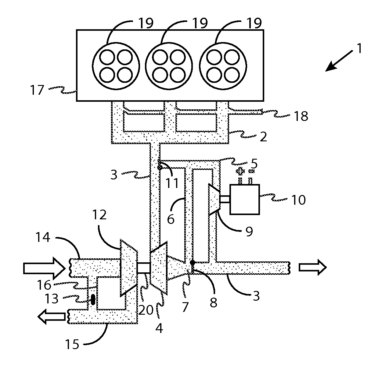
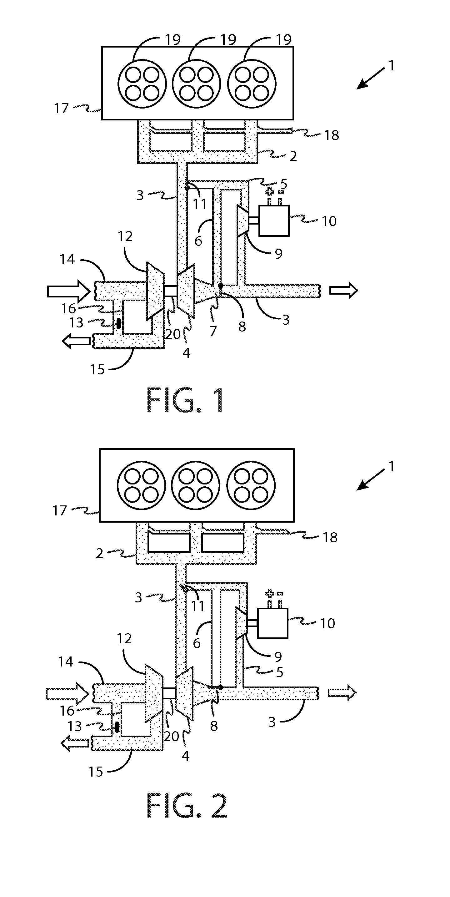
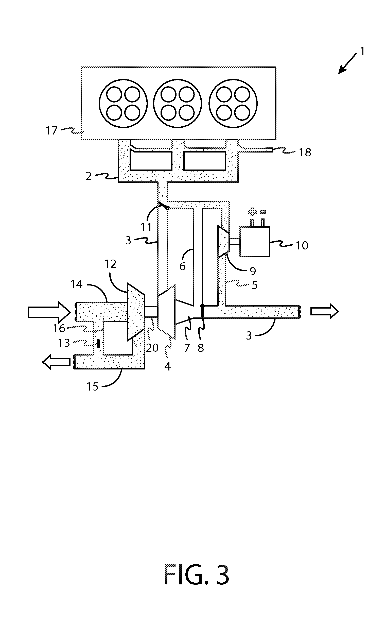
[0014]FIG. 1 shows a schematic diagram of an internal combustion engine 1, in which an exhaust gas manifold 2 is mounted on a cylinder head 17. In the exhaust manifold 2, the exhaust gases from the various combustion chambers 19 are collected and conducted to an exhaust gas line 3. In the exhaust gas line 3, an exhaust gas turbocharger 4 is installed, which is connected to a compressor 12 by a shaft 20. The present invention is suitable both for internal combustion engines with outside ignition and for those ignited by compression. During the operation of the internal combustion engine, the exhaust gas turbocharger 4 is subjected to a defined exhaust gas stream. As a result, the drive shaft 20 and thus also the compressor 12 are driven. By means of the compressor 12, combustion air is drawn in through the air intake line 14, compressed, and sent onward to the internal combustion engine 1 through the air charging line 15. Between the air intake line 14 and the air charging line 15, a...


PUM


Abstract

An internal combustion engine with an exhaust gas manifold, an exhaust gas line, an exhaust gas turbocharger, by which the compressor provided to charge combustion air for the internal combustion engine is driven, and a bypass line, which branches from the exhaust gas line and in which a power turbine is arranged, wherein a short-circuit line branches from the bypass line and leads to a section of the exhaust gas line located downstream of the exhaust gas turbocharger. In addition, a first valve is positioned in the section of the exhaust gas line located downstream of the exhaust gas turbocharger in such a way that exhaust gas leaving the exhaust gas turbocharger is diverted into the short-circuit line and then to the power turbine.

Description

CROSS REFERENCE TO RELATED APPLICATIONS[0001]This U.S. patent application claims priority to German Application DE 10 2008 064 521.4, filed Dec. 18, 2008, which is incorporated by reference herein in its entirety.FIELD OF THE INVENTION[0002]The invention pertains to an internal combustion engine with an exhaust gas turbocharger.BACKGROUND OF THE INVENTION[0003]In modern internal combustion engines with outside ignition, engine downsizing is achieved especially with the help of turbocharging. As a result, fuel consumption can be reduced, especially during the part-load driving cycles. The disadvantage of such a concept is the delayed response of the turbocharger, the so-called “turbo lag”, which means that it takes a certain amount of time for the torque to build when a load requirement is imposed. In the publication DE 37 29 117 C1, an internal combustion engine with an exhaust gas turbocharger and a power turbine is described, in which the power turbine is positioned in a bypass li...

Claims


Application Information

Patent Timeline
Patent Type & Authority Patents(United States)
IPC IPC(8): F02B33/44
CPCF01N5/04F02B37/18Y02T10/144Y02T10/16Y02T10/12
Inventor SCHWARZENTHAL, DIETMARHEMMERLEIN, NORBERTMULLER, STEPHAN
Owner DR ING H C F PORSCHE AG
Why Eureka
Try Eureka