Device for stabilizing a vertebral joint and method for anterior insertion thereof

a technology for stabilizing devices and vertebrae joints, applied in the field of spinal prostheses and surgical methods, can solve the problems of accelerating degeneration of spinal segments, further injury to other components of the spine, irreversible procedures, etc., and achieves the effect of reducing wear

Active Publication Date: 2013-10-15
GLOBUS MEDICAL INC
View PDF9 Cites 18 Cited by
  • Summary
  • Abstract
  • Description
  • Claims
  • Application Information

AI Technical Summary

Benefits of technology

[0014]By being staggered, the motion limiting members on the superior endplate can enmesh with the motion limiting members on the inferior endplate. In addition, by being staggered and enmeshed the motion limiting members can move in a limited amount relative to each other until they contact each other. The staggered positioning allows the six degrees of freedom discussed previously while simultaneously can limit the amount of freedom in those degrees of freedom.
[0015]According to a further aspect of the invention, the body has a height, and the motion limiting members on the endplates are generally shorter than the body. By being shorter than the body, the body may still compress by the difference in heights before a motion limiting member on an opposing endplate contacts the opposing endplate. In general, such a feature minimizes wear from rubbing between the endplate and the opposing motion limiting member. It also limits movements and prevents the body from being compressed to an extreme thinness.
[0016]According to a further aspect of the invention, a motion limiting member on the superior endplate is disposed on the same side of the body as a motion limiting member on the inferior endplate. By having a motion limiting member on the superior endplate and the inferior endplate, the body is secured on the given side by the motion limiting members and cannot slip from the superior endplate and the inferior endplate. Additional pairs (i.e. a superior and an inferior) of motion limiting members can be disposed about a periphery of the endplates to secure the body between the endplates.
[0018]According to a further aspect of the invention, the endplate can have at least one bore to promote bone growth therethrough. The bore can be a single large bore. Alternative, a plurality of smaller bores can be formed in each endplate. Bone will generally grow into the bore and help to secure the prosthesis to the adjacent vertebra.
[0030]A fastener can be inserted through the body and into a vertebra to stabilize being connected to said body and configured to insert into a vertebra. The fastener can fix and stabilize the body relative to the vertebra.
[0032]The motion limiting members disposed on the superior endplate can be staggered with regard to the motion limiting members disposed on the inferior endplate. “Staggered” is generally meant to mean that the motion limiting members are offset from each other with reference to vertical alignment. In other words, a motion limiting member on the top does not align vertically with a motion limiting member on the top. In addition, a gap can be left between adjacent superior and inferior motion limiting members. The gap in the staggered motion limiting members allows for a desired amount of play to allow for freedom of movement of one endplate relative to another. The amount of play can be controlled by adjusting the width of the gaps. By being staggered, the motion limiting members on the superior endplate can enmesh with the motion limiting members on the inferior endplate.

Problems solved by technology

Components of a motion segment that move out of position or become damaged can lead to serious pain and may lead to further injury to other components of the spine.
Underlying causes of structural changes in the motion segment unit leading to instability include trauma, degeneration, aging, disease, surgery, and the like.
There are several disadvantages to fusion, however.
In addition to a loss of mobility, fusion also causes the mobility of the motion segment to be transferred to other motion segments of the spine.
The added stresses transferred to motion segments neighboring or nearby the fused segment can cause or accelerate degeneration of those segments.
One other disadvantage to fusion is that it is an irreversible procedure.
In addition, it is believed that fusion of a motion segment has a clinical success of approximately seventy percent (˜70%), and often does not alleviate pain experienced by the patient.
Analysis of fusion systems going back to the early 1960's has shown that the intentionally rigid designs have often caused stress concentrations and have directly and indirectly contributed to the degeneration of the joints above and below the fusion site (as well as at the fusion site itself).
Finally, removal of portions of the motion segment unit reduces the amount of support available for the affected motion segment unit.
The device is said to be “substantially” equal to the height of the disc because the original disc might be compressed or damaged.
The device is said to be “substantially” equal to the height of the vertebra because the original vertebra and / or discs might be compressed or damaged.

Method used


Image

  • Device for stabilizing a vertebral joint and method for anterior insertion thereof
  • Device for stabilizing a vertebral joint and method for anterior insertion thereof
  • Device for stabilizing a vertebral joint and method for anterior insertion thereof

Examples


Embodiment Construction

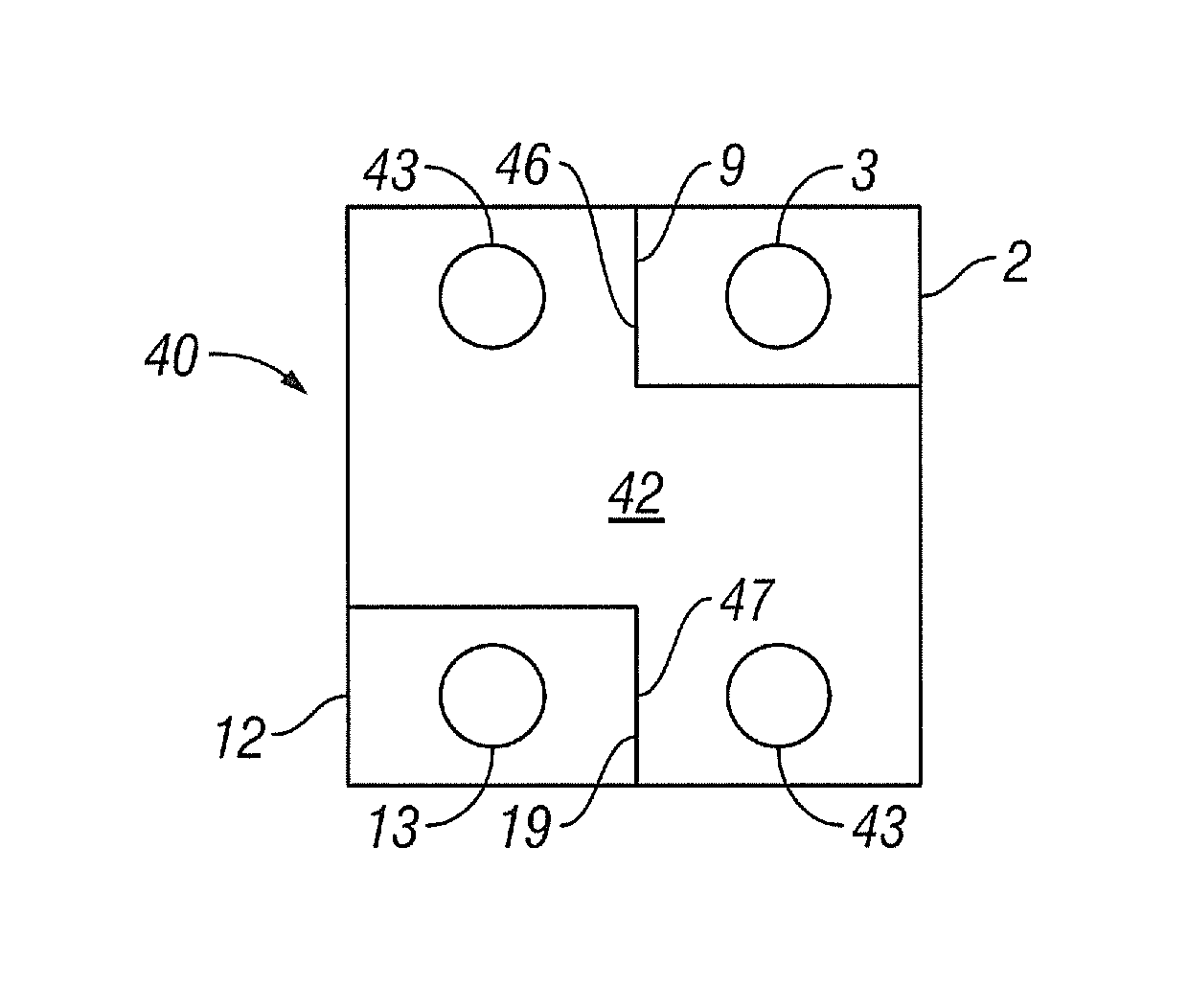
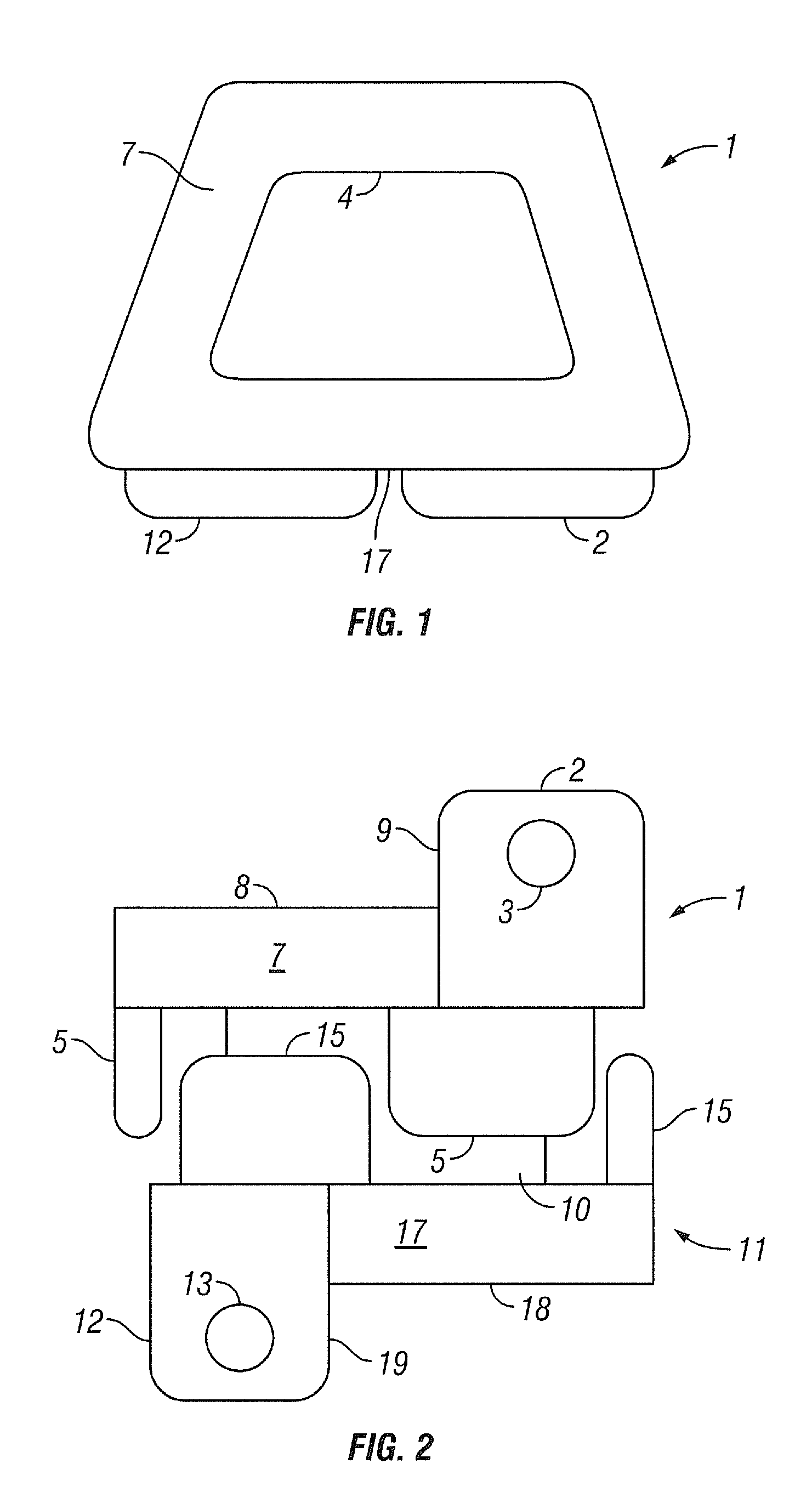
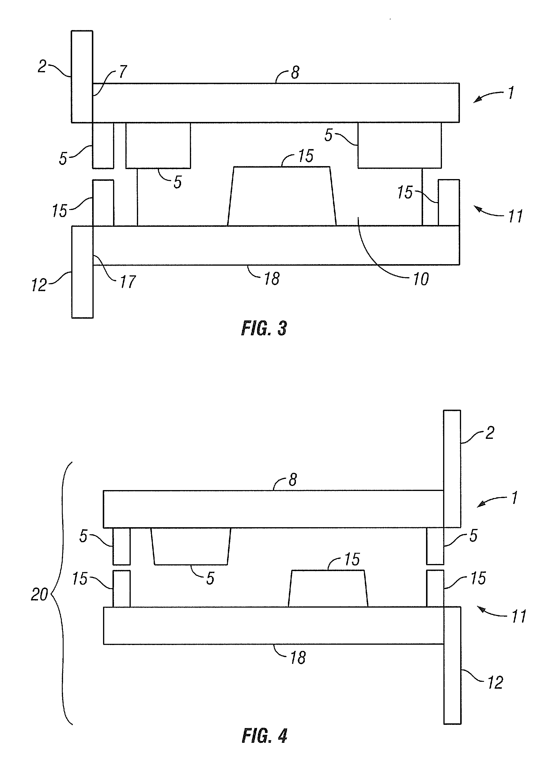
[0058]Referring now to the figures of the drawing in detail and first, particularly, to FIGS. 1-6 thereof, there is seen a device 20 for stabilizing a first bone of a joint relative to a second bone of a joint. In particular, the device 20 is useful for stabilizing a first vertebra relative to a second vertebra following discectomies or corpectomies. The device 20 includes a superior endplate 1 and inferior endplate 11. As shown in FIG. 15, the superior endplate 1 is configured to support a superior vertebra 101. The inferior endplate 11 is configured to support an inferior vertebra 111. In one embodiment, a superior surface 8 of the superior endplate 1 is textured to increase friction between the superior vertebra 101 and the superior endplate 1. Likewise, the inferior surface 18 of the inferior endplate 11 is textured. The textured surface can include teeth, ridges, and / or grooves. These protrusions extend from a bone engaging surface of the device and engage bone of the joint to ...


PUM


Abstract

A prosthetic device can be used as a prosthesis following a discectomy or a corpectomy. The prosthetic device includes two endplates with staggered motion limiting members. The device can be configured to allow six degrees of motion when comparing one endplate relative to the other. The endplates can be configured to fix the joint by changing the body held within the device and by adding a locking plate and fasteners. A method teaches how to insert a device to an intervertebral space via an anterior incision.

Description

FIELD OF THE INVENTION[0001]The present disclosure generally relates to spinal prostheses and surgical methods for inserting spinal prostheses.BACKGROUND OF THE INVENTION[0002]The spine includes a series of joints routinely called motion segment units. Motion segment units are the smallest component of the spine that exhibit kinematic behavior characteristic of the entire spine. The motion segment unit is capable of flexion, extension, lateral bending, and translation. The components of each motion segment unit include two adjacent vertebrae and their apophyseal joints, the intervertebral disc, and the connecting ligamentous tissue. Each component of the motion segment unit contributes to the mechanical stability of the joint.[0003]Components of a motion segment that move out of position or become damaged can lead to serious pain and may lead to further injury to other components of the spine. Depending upon the severity of the structural changes that occur, treatment may include fu...

Claims


Application Information

Patent Timeline
Patent Type & Authority Patents(United States)
IPC IPC(8): A61F2/44
CPCA61F2/44A61B17/86A61F2002/30578A61F2/4455A61F2220/0025A61F2002/30904A61F2310/00023A61F2002/30841A61F2002/30507
Inventor SUH, SEANSUH, JONKUNJACHAN, VIPINPAUL, DAVID C.
Owner GLOBUS MEDICAL INC
Why Eureka
Try Eureka