Composite pressure vessel including crack arresting barrier

a technology of crack-absorption barrier and composite structure, which is applied in the direction of vessel construction details, transportation and packaging, mechanical equipment, etc., can solve the problems of matrix resin crack growth in such composite structure, affecting structural integrity, and traveling along the ordered fiber windings, etc., and achieves the effect of resisting crack growth

Active Publication Date: 2013-10-22
NASA
View PDF30 Cites 9 Cited by
  • Summary
  • Abstract
  • Description
  • Claims
  • Application Information

AI Technical Summary

Benefits of technology

[0007]Accordingly, it is an object of the present inven

Problems solved by technology

Current micro-crack studies have demonstrated that crack growth in such composite structures occurs in the matrix resin and travels along the ordered fiber

Method used


Image

  • Composite pressure vessel including crack arresting barrier
  • Composite pressure vessel including crack arresting barrier

Examples


Embodiment Construction

)

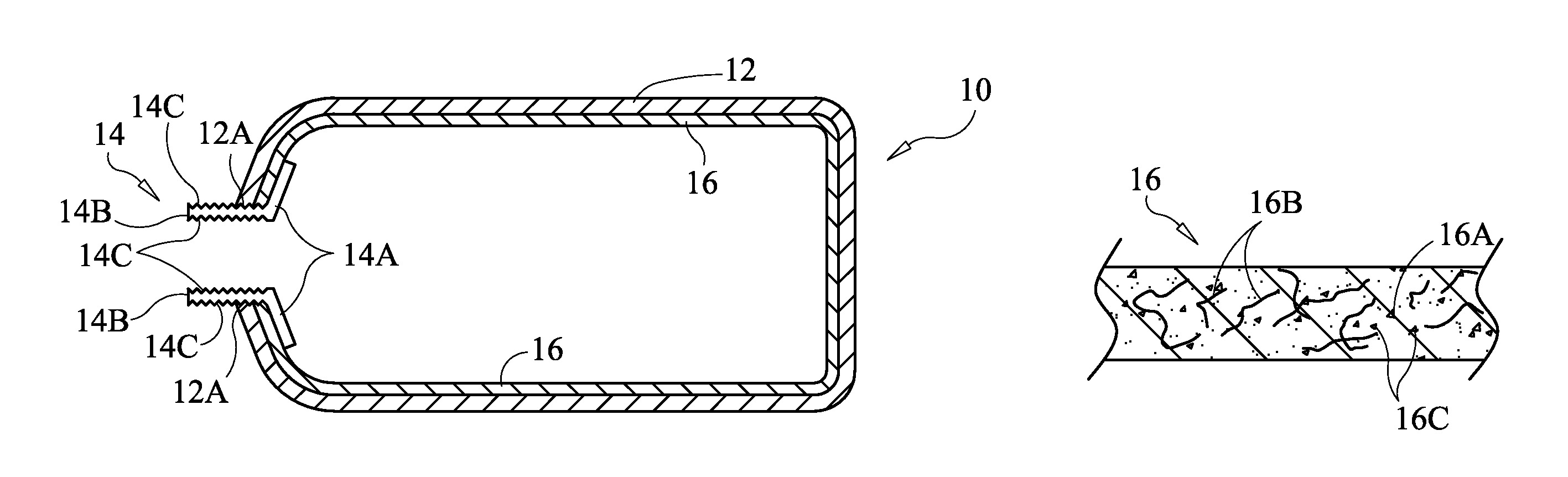
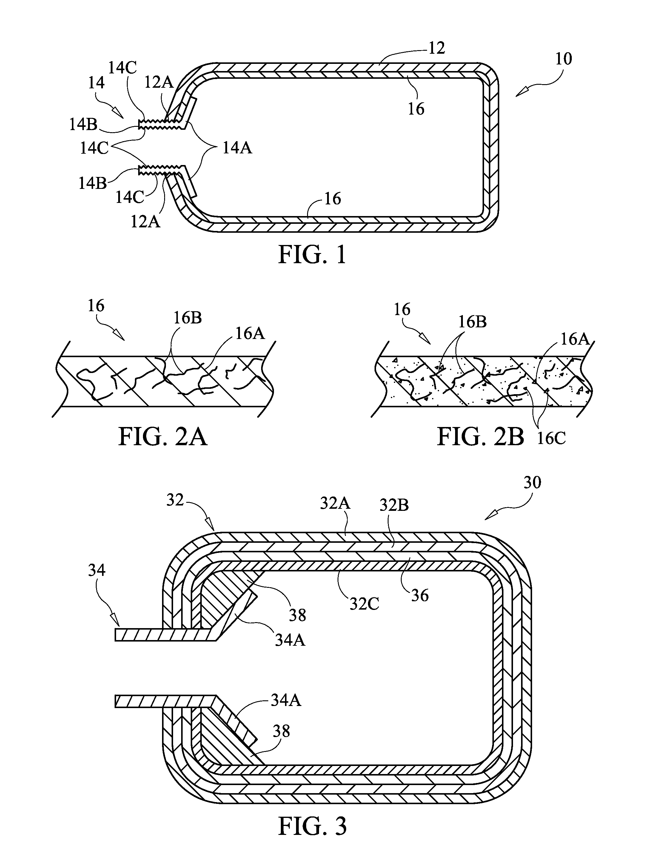
[0017]Referring now to the drawings and more particularly to FIG. 1, a pressure vessel that includes a crack arresting barrier in accordance with the present invention is illustrated in cross-section and is referenced generally by numeral 10. The size and shape of pressure vessel 10 are not limitations of the present invention as size / shape are typically dictated by the particular application. In general, pressure vessel 10 can be used to contain a fluid material (e.g., gas or liquid) under pressure.

[0018]In the illustrated embodiment, pressure vessel 10 includes an outer rigid tank 12 that can be constructed in accordance with a variety of known processes / materials. For example, if pressure vessel 10 is to contain cryogenic fluids, tank 12 could be a composite wrapped structure, i.e., an orderly arrangement of fiber (e.g., carbon fiber) wraps held together in a rigid fashion by a resin matrix that permeates the fiber wraps. Tank 12 has an open-end 12A for receiving a fitting 14 th...


PUM

PropertyMeasurementUnit
Fractionaaaaaaaaaa
Pressureaaaaaaaaaa

Abstract

A pressure vessel includes a ported fitting having an annular flange formed on an end thereof and a tank that envelopes the annular flange. A crack arresting barrier is bonded to and forming a lining of the tank within the outer surface thereof. The crack arresting barrier includes a cured resin having a post-curing ductility rating of at least approximately 60% through the cured resin, and further includes randomly-oriented fibers positioned in and throughout the cured resin.

Description

CROSS-REFERENCES TO RELATED APPLICATIONS[0001]This application is a continuation application of U.S. patent application Ser. No. 12 / 604,954, filed on Oct. 23, 2009 now abandoned.ORIGIN OF THE INVENTION[0002]The invention described herein was made by an employee of the United States Government and may be manufactured and used by or for the Government of the United States of America for governmental purposes without the payment of any royalties thereon or therefor.BACKGROUND OF THE INVENTION[0003]1. Field of the Invention[0004]This invention relates to pressure vessels. More specifically, the invention is a composite pressure vessel that includes a crack arresting barrier as part thereof.[0005]2. Description of the Related Art[0006]The aerospace industry relies heavily on the structural integrity of composite-based, cryogenic-fluid (e.g., liquid hydrogen) storage tanks for its space vehicles. Accordingly, the aerospace industry is very concerned about the formation and propagation of ...

Claims


Application Information

Patent Timeline
IPC IPC(8): F17C1/06F17C1/16
CPCF17C1/16F17C1/06F17C1/00F17C2201/0109F17C2201/0119F17C2203/0604F17C2203/0607F17C2203/0619F17C2203/0624F17C2203/0663F17C2203/0697F17C2221/012F17C2223/0123F17C2223/0161F17C2260/011F17C2270/0189F17C2270/0194F17C2205/0305Y02E60/32
Inventor DELAY, THOMAS K.
Owner NASA
Why Eureka
Try Eureka