Paving machine with a storage container

a technology of a storage container and a paving machine, which is applied in the direction of roads, roads, construction, etc., can solve the problem of no subsequent support device provided, and achieve the effect of promoting the downward transportation of materials and facilitating the positioning at a new paving si

Inactive Publication Date: 2013-10-22
SMG SPORTPLATZMACHINEBAU GMBH
View PDF19 Cites 10 Cited by
  • Summary
  • Abstract
  • Description
  • Claims
  • Application Information

AI Technical Summary

Benefits of technology

[0008]Now, the material is poured into a storage container which is then filled up with the given volume mass, so that a certain area can be paved without replenishment. In the state of the art, the situation was such that material had to be replenished continually by means of appropriate dump trucks, and it was in fact distributed with appropriate tools. An appropriately dimensioned storage container is now provided, which makes it possible, for example, to pave a distance two to three or four to five times the length of the paving machine itself in one process respectively one work step without interruption. An additional advantage is provided by the solution according to the invention, in which the storage container including the material is located on the device above the fill-up area. As a result, a certain weight is also added to the device respectively the paving machine, which ensures that the paving machine overall presents an excellent directional stability. Since the carriages can now no longer be soiled by the paving material, the quality in this regard can be increased considerably. The need for reworking is considerably reduced or eliminated entirely. An additional advantage is that the fill-up can be achieved over the entire paving width, that is the width of the flattening plank. As a result, the marginal areas are supplied considerably better with material, resulting here too in a quality improvement and / or facilitation of the activity of the operating personnel. The risk of accidents is reduced, because handling in the paving direction in front of the paving machine is no longer needed.
[0032]It should be mentioned that the paving machine according to the invention naturally also has an appropriate transport device in order to transport the device to the paving site or away from the paving site. Said device consists, for example, of wheels with adjustable height, which, when positioned, lift the paving machine from the surface, so that the carriage is no longer in contact with the floor. By means of the, for example, four wheels respectively rollers, the transport away respectively the positioning at a new paving site is considerably favored.

Problems solved by technology

In addition, no subsequent support device is provided, and instead at least the entire work width is available as paving width.

Method used


Image

  • Paving machine with a storage container
  • Paving machine with a storage container
  • Paving machine with a storage container

Examples


Embodiment Construction

[0035]In the figures, identical or corresponding elements are in each case provided with the same references, and, unless necessary, they are not described again.

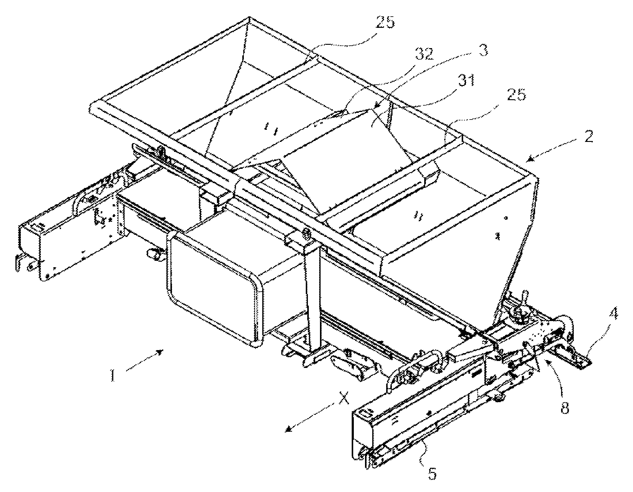
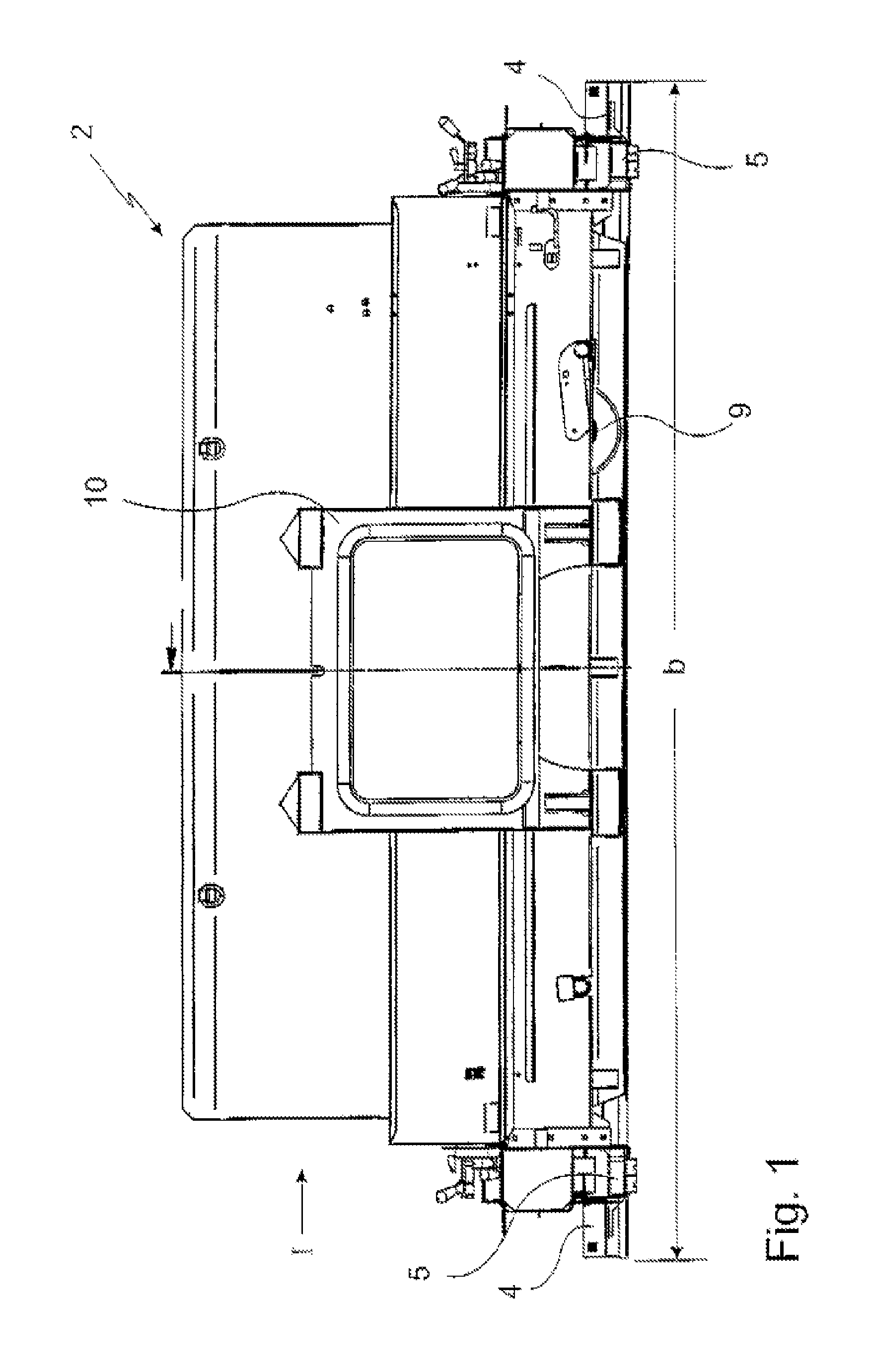
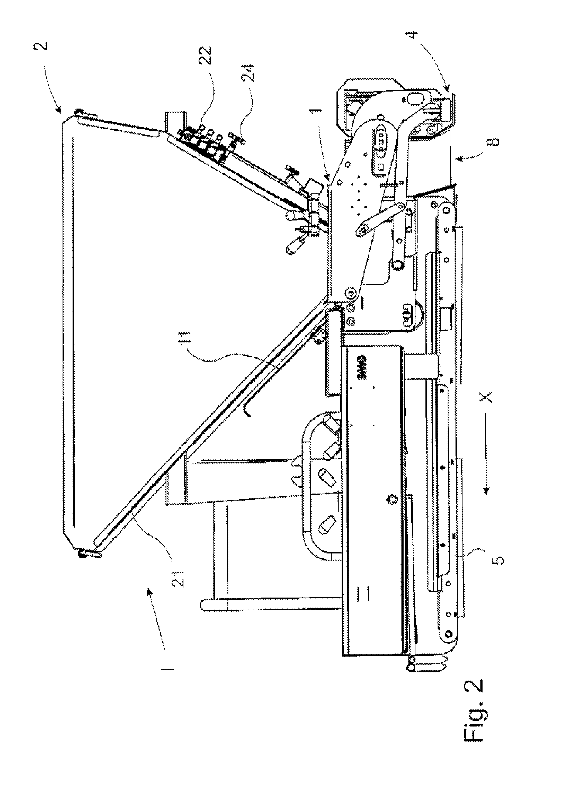
[0036]FIGS. 1-4 shows different views of the paving machine I according to the invention. Here, in FIG. 1, a front view is shown, in FIG. 2 a side view, while FIG. 3 shows a cross-sectional representation of the side view, and FIG. 4 a three-dimensional representation of the paving machine according to the invention. The paving machine overall is marked with the reference I. As can be seen, the storage container 2 is arranged on the paving machine I. Said container is provided diagrammatically with an arrow and the reference 2. The carriage 5 is located in front of the flattening plank 4, in the travel direction X. Said carriage is designed, for example, as a chain carriage, and it is consequently accommodated in a type of chain case. It is also clearly apparent that, for transporting the device into and out of the fill-in ...


PUM


Abstract

The invention relates to a self-propelled paving machine for floor coverings respectively cover layers, particularly for synthetic floor coverings respectively resilient base layers, for synthetic coverings for sports surfaces, such as jogging tracks, small playing fields, runways for long jump installations, playgrounds, screed, particularly synthetic resin screed or the like, wherein the material is distributed uniformly over a fill-in width on a prepared under-floor, and pulled off or flattened there by at least one flattening plank, wherein a storage container is provided which is connected with a fill-up area of the paving machine, and the paving machine presents a carriage, and wherein the fill-up area is provided between a rear closing-off of the carriage, viewed in the travel direction, and the flattening plank, wherein a direct delivery of the material from the storage container into the fill-up area is provided.

Description

FIELD OF THE INVENTION[0001]The invention relates to a paving machine for floor coverings respectively cover layers, particularly for synthetic floor coverings respectively resilient base layers, for synthetic coverings for sports surfaces, such as jogging tracks, small playing fields, runways for long jump installations, playgrounds, screed or the like.BACKGROUND OF THE INVENTION[0002]In the state of the art it is known that such paving machines can be used, for example, for producing cover layers with synthetic coverings. For this purpose, the material which forms the cover layer is mixed in a mixer or mixing apparatus, and then distributed by a paving machine. Here, the paving machine is designed in such a manner that it has a distribution shield which distributes the material that lies in the paving direction before the paving machine, approximately at the height of the synthetic layer, before the hardening of the latter respectively solidification. The problem here is that the ...

Claims


Application Information

Patent Timeline
Patent Type & Authority Patents(United States)
IPC IPC(8): E01C19/20
CPCE01C19/48
Inventor OWEGESER, JOHANN
Owner SMG SPORTPLATZMACHINEBAU GMBH
Why Eureka
Try Eureka