
High voltage-resistant lateral double-diffused transistor based on nanowire device

a mos transistor, high-voltage-resistant technology, applied in the direction of nanotechnology, semiconductor devices, electrical equipment, etc., can solve the problems of reducing the precision of output current, increasing the cost and yield, increasing the off-state current and transconductance of the device, etc., to improve the gate control capability of the silicon nanowire device, reducing the breakdown voltage of the mos transistor, and improving the efficiency of the devi

Active Publication Date: 2013-10-22
SEMICON MFG INT (SHANGHAI) CORP +1
View PDF6 Cites 9 Cited by
  • Summary
  • Abstract
  • Description
  • Claims
  • Application Information

AI Technical Summary

Benefits of technology

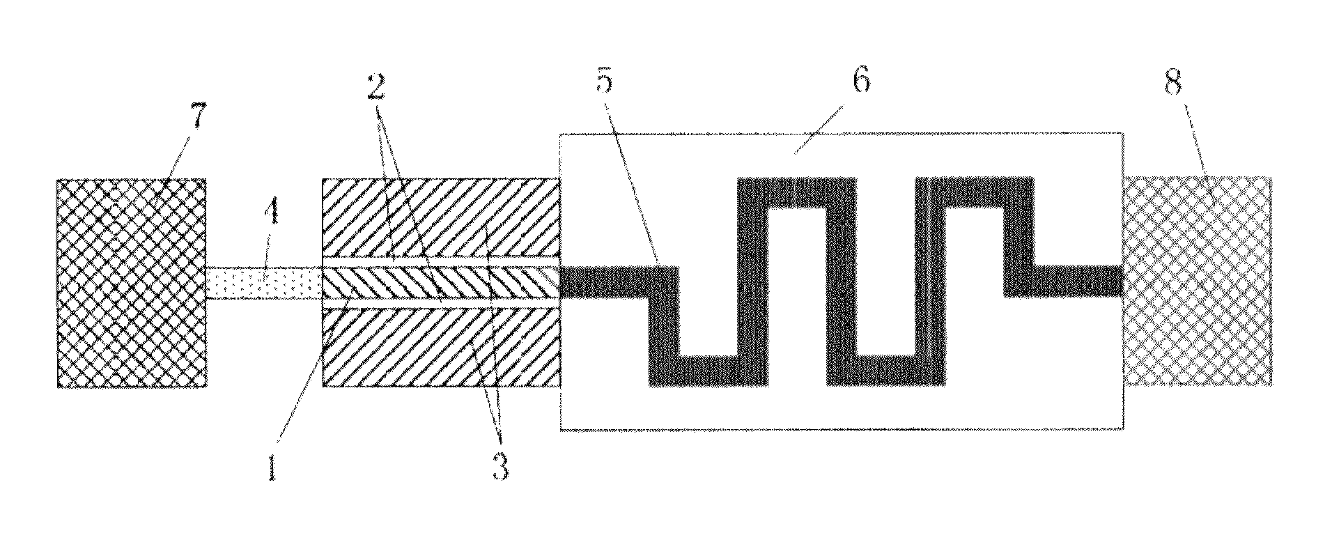
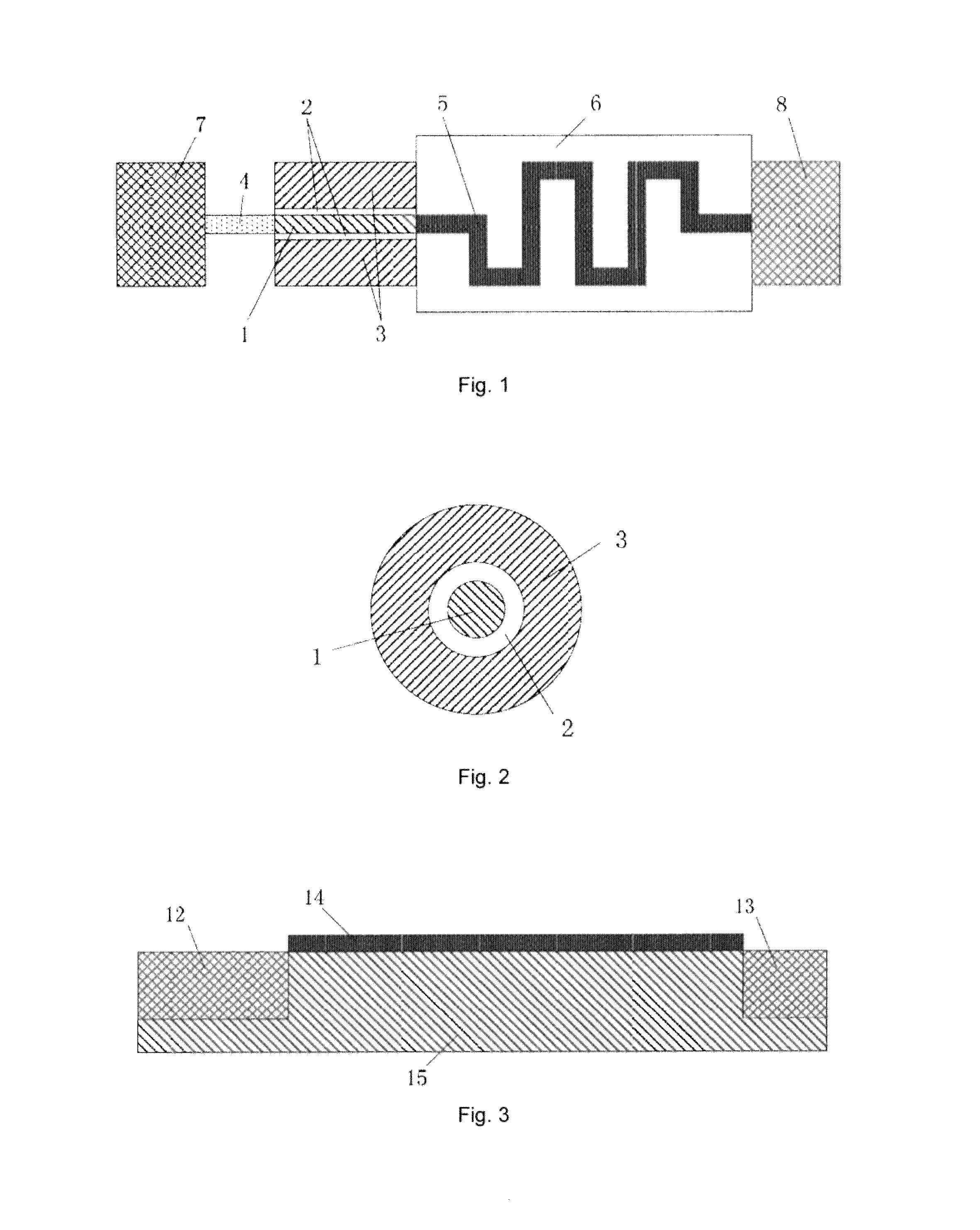
[0017]A lateral double-diffused transistor suitable for an RF power amplifier or other high-voltage circuits is manufactured based on a silicon nanowire MOS transistor, so that the drain / substrate current introduced into a planar LDMOS due to the large drain / substrate voltage is avoided, and it is avoided that the drain / substrate conjunction reverse breakdown decreases the breakdown voltage of the LDMOS. At the same time, because of the excellent gate control capability of the silicon nanowire device, the off-state current is reduced, and a relatively large transconductance may be obtained. The drain end S-shaped drifting region plays the role of generating more potential drops in the insulating material surrounding the back-tracks via a multiple back-track S-shaped structure with a low doping concentration and the material with a low relative dielectric constant filled between the S-shaped back-tracks, so that the maximum electric-field intensity in the direction of the carrier path from the channel region to the drain region is reduced, the electric field distribution in direction of the carrier path is uniform, and the avalanche breakdown effect that may be caused by a high intensity electric field is avoided, which is favourable to increase the breakdown voltage of an element.

Problems solved by technology

Although the planar lateral double-diffused field effect transistor is compatible with the conventional CMOS process, under the background that the improvement of the key processing steps such as lithographying in the CMOS process is limited and the object of batch production via advanced technologies cannot be attained, the structure of the planar transistor causes a continual increase of cost and a reduction of the yield.
At present, taking 45 nm flat tube process as an example, the technology has reached the process limit, and a serious short channel effect will be introduced into the flat tube, which results in an increase of the off-state current and a reduction of transconductance in the device.
At the same time, since a lateral double-diffused field effect transistor with a planar-structure has a large drain / substrate conjunction reverse bias during the normal operation, a large drain / substrate leakage current exists, which affects the precision of the output current, and the large drain / substrate reverse bias may even result in the device is brokendown soon and thus reduce the high voltage-resistant capability of the LDMOS.

Method used


Image

  • High voltage-resistant lateral double-diffused transistor based on nanowire device
  • High voltage-resistant lateral double-diffused transistor based on nanowire device
  • High voltage-resistant lateral double-diffused transistor based on nanowire device

Examples


Embodiment Construction

[0037]The invention will be further described in detail below with combination of the drawings and specific embodiments.

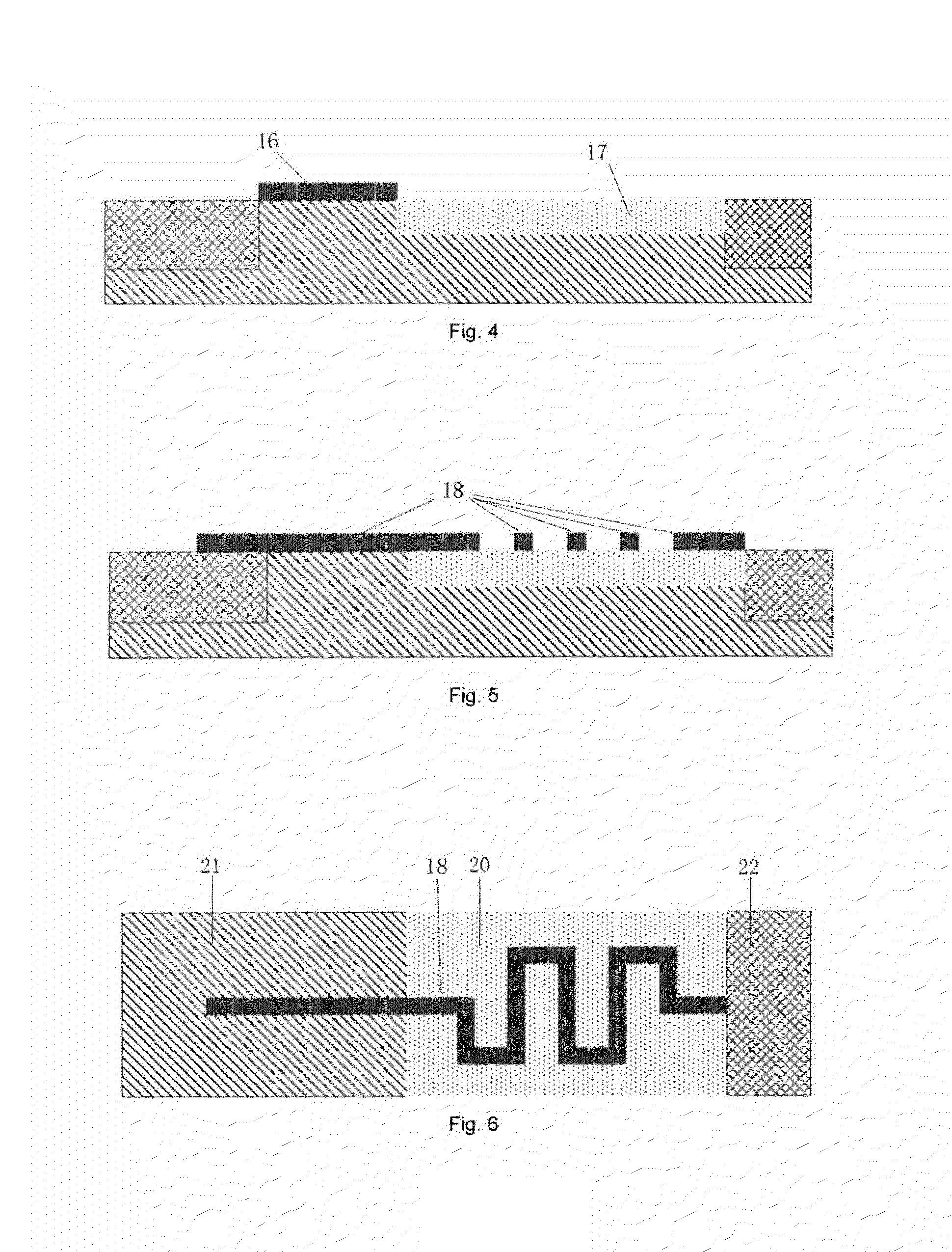
[0038]FIG. 1 is a schematic plan view of the cross-section of the core part of a lateral double-diffused transistor based on a silicon nanowire MOS transistor according to the invention. The difference between the structure of the transistor and that of a conventional silicon nanowire MOS transistor lies in that.

[0039]1) The connection mode between the channel part and the drain region: in the invention, the drain end S-shaped drifting region is used as the connection part, the shape characteristic of which is S-shaped.

[0040]2) The connection region between the channel part and the drain region (in the invention, the connection region is the drain end S-shaped drifting region): the doping concentration is different, and the doping concentration of the invention is lower than that of the conventional nanowire MOS transistor; and

[0041]3) The invention discloses that ...


PUM


Abstract

The invention provides a high voltage-resistant lateral double-diffused transistor. The lateral double-diffused MOS transistor includes a channel region, a gate dielectric, a gate region, a source region, a drain region, a source end extension region and a drain end S-shaped drifting region, wherein the channel region has a lateral cylindrical silicon nanowire structure, on which a layer of gate dielectric is uniformly covered, the gate region is on the gate dielectric, the gate region and the gate dielectric completely surround the channel region, the source end extension region lies between the source region and the channel region, the drain end S-shaped drifting region lies between the drain region and the channel region, the plan view of the drain end S-shaped drifting region is in the form of single or multiple S-shaped structure(s), and an insulating material with a relative dielectric constant of 1-4 is filled within the S-shaped structure(s).

Description

CROSS-REFERENCE TO RELATED APPLICATIONS[0001]This application is a national stage application under 35 U.S.C. §371 of International Application No. PCT / CN2011 / 072395, filed Apr. 1, 2011, which in turn claims priority under 35 U.S.C. §119(a) to Chinese Patent Application No. 201110029706.7, filed Jan. 27, 2011, the contents of which are hereby incorporated by reference into the present disclosure.FIELD OF THE INVENTION[0002]The present invention relates to a lateral double-diffused MOS transistors in the field of microelectronics semiconductor devices, and in particular, to a lateral double-diffused transistor based on a silicon nanowire MOS transistor, which is suitable for application in a radio frequency (RF) power amplifier or other high-voltage circuits.BACKGROUND OF THE INVENTION[0003]With the development of RF circuits, RF devices gain more and more attention in radio communications, for example, personal / commercial radio communication apparatus, mobile communication apparatus...

Claims


Application Information

Patent Timeline
Patent Type & Authority Patents(United States)
IPC IPC(8): H01L29/76
CPCB82Y10/00H01L29/0649H01L29/0673H01L29/0692H01L29/16H01L29/66439H01L29/775
Inventor HUANG, RUZOU, JIBINWANG, RUNSHENGYANG, GENGYUAI, YUJIEFAN, JIEWEN
Owner SEMICON MFG INT (SHANGHAI) CORP
Learn More