Motor structure

a technology of motor structure and rotor core, which is applied in the direction of dynamo-electric machines, electrical apparatus, magnetic circuit shapes/forms/construction, etc., can solve problems affecting the service performance of motors, achieve the effects of reducing the magnetic leakage of the rotor core, improving the service performance, and reducing the ripple of cogging torqu

Active Publication Date: 2013-10-22
ZHONGSHAN BROAD OCEAN MOTOR MFG
View PDF8 Cites 10 Cited by
  • Summary
  • Abstract
  • Description
  • Claims
  • Application Information

AI Technical Summary

Benefits of technology

[0006]In view of the above-described problems, it is one objective of the invention to provide a motor structure that has a simple structure, low magnetic leakage between the stator and rotor teeth, low cogging torque ripple, big counter-electromotive force constant, smooth waveform of counter-electromotive force, high service performance, and low loss.
[0017]1) the rotor core comprises the annular ring having the central axial pore and a plurality of magnetic induction blocks protruding outwards from the outer side of the annular ring, two adjacent magnetic induction blocks form the radial recess for mounting the permanent magnet, the magnetic induction blocks at both sides of the opening of the radial recess protrude with a hook block, the section of the outer side surface of the magnetic induction blocks is a circular-arc line and the outer side surface employs a point with a distance deviating from the center of the central axial pore as the center of circle. Such structure is helpful to reduce magnetic leakage of the rotor core, lower cogging torque ripple, and achieve big counter-electromotive force constant and smooth waveform of the counter-electromotive force. Therefore, the motor's performance has been improved and losses have been reduced;
[0018]2) the inner side surface of the teeth comprises the incurvate outer arc line in the middle and the outer cutting edge at both sides, the outer side surface of the magnetic induction blocks cooperates with the inner side surface of the teeth and the outer arc line is a circular-arc line. Such construction helps to further reduce magnetic leakage and lower the cogging torque ripple;
[0019]3) the distance deviating from the center of the central axial pore is 5-20 mm, the maximum external diameter of the rotor core is 80-90 mm, external diameter of the stator core is 135-145 mm, diameter of the inner circular hole of the stator core is 82-92 mm and bigger than the maximum external diameter of the rotor core; the outer side edge of the stator core is configured with a plurality of cut lines, and the mounting hole is arranged on the stator core and close to the cut lines; the number of the teeth is 12 and the number of the magnetic induction blocks and the permanent magnets are 10. The performance of the stator core and the rotor core can be optimized under the consistent performance. Moreover, materials are saved and thus product costs reduced; and
[0020]4) the distance between the two hook blocks arranged at the opening of the same radial recess is 3.5-5 mm and a convex plate is arranged at the middle bottom of the radial recess, thus it can further reduce the magnetic leakage and lower the cogging torque ripple.

Problems solved by technology

Such structure has the disadvantages of higher stator's cogging torque, larger magnetic leakage between the stator and rotor teeth, and distorted top waveform of counter-electromotive force, thereby affecting the motor's service performance.

Method used


Image

  • Motor structure
  • Motor structure
  • Motor structure

Examples


Embodiment Construction

[0030]The invention is explained in further detail below with reference to the accompanying drawings and embodiments.

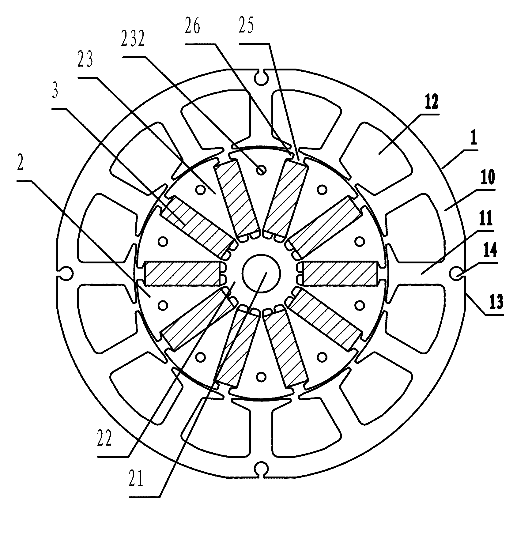
[0031]As shown in FIGS. 3-8, a motor structure provided by the invention comprises a stator assembly and a rotor assembly embedded therein. The stator assembly comprises a stator core 1 and a winding. The stator core 1 comprises a yoke 10 and a plurality of teeth 11 protruding inwards from the yoke 10. Two adjacent teeth 11 form a wire embedding slot 12. The winding is placed inside the wire embedding slot 12 and winds around the teeth 11. The rotor assembly comprises a rotor core 2 and a permanent magnet 3. The rotor core 2 comprises an annular ring 22 having a central axial pore 21 and a plurality of magnetic induction blocks 23 protruding outwards from an outer side of the annular ring 22. Two adjacent magnetic induction blocks 23 form a radial recess 24 for mounting the permanent magnet 3. The magnetic induction blocks 23 at both sides of the opening 25 of the rad...


PUM


Abstract

A motor structure including a stator assembly having a stator core and a winding and a rotor assembly embedded therein having a rotor core and a permanent magnet. The stator core includes a yoke and a plurality of teeth protruding inwards from the yoke. Two adjacent teeth form a wire embedding slot and the winding is placed inside the wire embedding slot and winds around the teeth. The rotor core includes an annular ring having a central axial pore and a plurality of magnetic induction blocks protruding outwards from an outer side of the annular ring. Two adjacent magnetic induction blocks form a radial recess for mounting the permanent magnet. The section of an outer side surface of the magnetic induction blocks is a circular-arc line. The outer side surface employs a point with a distance deviating from the center of the central axial pore as a center of circle.

Description

CROSS-REFERENCE TO RELATED APPLICATIONS[0001]Pursuant to 35 U.S.C. §119 and the Paris Convention Treaty, this application claims the benefit of Chinese Patent Application No. 201110229712.7 filed Aug. 11, 2011, the contents of which are incorporated herein by reference.BACKGROUND OF THE INVENTION[0002]1. Field of the Invention[0003]The invention relates to a motor structure.[0004]2. Description of the Related Art[0005]As shown in FIG. 1 and FIG. 2, a conventional motor structure includes a stator assembly and a rotor assembly. The stator assembly includes a stator core 1 and a winding. The stator core 1 includes a yoke 10 and a plurality of teeth 11 protruding inwards from the yoke 10. Two adjacent teeth 11 form a wire embedding slot 12. The winding is placed inside the wire embedding slot 12 and winds around the teeth 11. The rotor assembly includes a rotor core 2 and a permanent magnet 3. The rotor core 2 includes an annular ring 21 having a central axial pore 20 and a plurality o...

Claims


Application Information

Patent Timeline
Patent Type & Authority Patents(United States)
IPC IPC(8): H02K21/12
CPCH02K21/16H02K1/146H02K1/2773H02K2213/03
Inventor PAN, MINGPAN
Owner ZHONGSHAN BROAD OCEAN MOTOR MFG
Why Eureka
Try Eureka