
Pad controlling apparatus

a control apparatus and pad technology, applied in the direction of process and machine control, power supply for data processing, instruments, etc., can solve the problems of reducing the voltage applied to the pad, the pad mounted thereon does not normally operate, and the pad is quickly flown to the pad, so as to minimize the leakage current

Inactive Publication Date: 2013-10-22
SAMSUNG ELECTRO MECHANICS CO LTD
View PDF8 Cites 3 Cited by
  • Summary
  • Abstract
  • Description
  • Claims
  • Application Information

AI Technical Summary

Benefits of technology

The apparatus ensures normal chip operation during external interrupts by maintaining voltage above a predetermined level and reduces leakage current in standby modes by strategically bypassing current through the switching unit.

Problems solved by technology

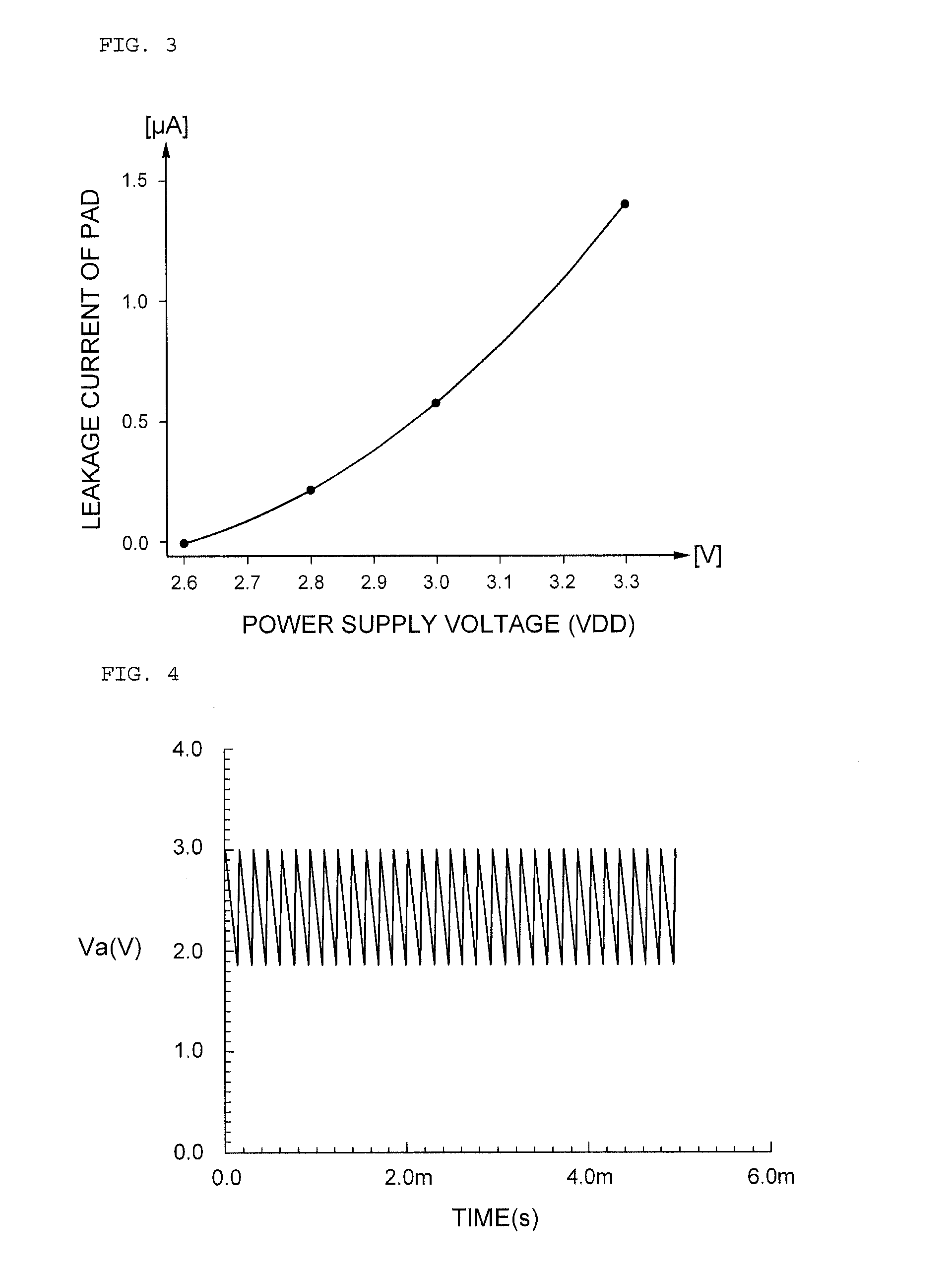
However, in the case in which sudden interrupt occurs from the outside, a large amount of current rapidly flows to the pad and voltage applied to the pad is thus decreased significantly, such that a chip having the pad mounted thereon does not normally operate.

Method used


Image

  • Pad controlling apparatus
  • Pad controlling apparatus
  • Pad controlling apparatus

Examples


Embodiment Construction

[0026]The terms and words used in the present specification and claims should not be interpreted as being limited to typical meanings or dictionary definitions, but should be interpreted as having meanings and concepts relevant to the technical scope of the present invention based on the rule according to which an inventor can appropriately define the concept of the term to describe most appropriately the best method he or she knows for carrying out the invention.

[0027]Therefore, the configurations described in the embodiments and drawings of the present invention are merely most preferable embodiments but do not represent all of the technical spirit of the present invention. Thus, the present invention should be construed as including all the changes, equivalents, and substitutions included in the spirit and scope of the present invention at the time of filing this application.

[0028]Hereinafter, exemplary embodiments of the present invention will be described in detail with referen...


PUM


Abstract

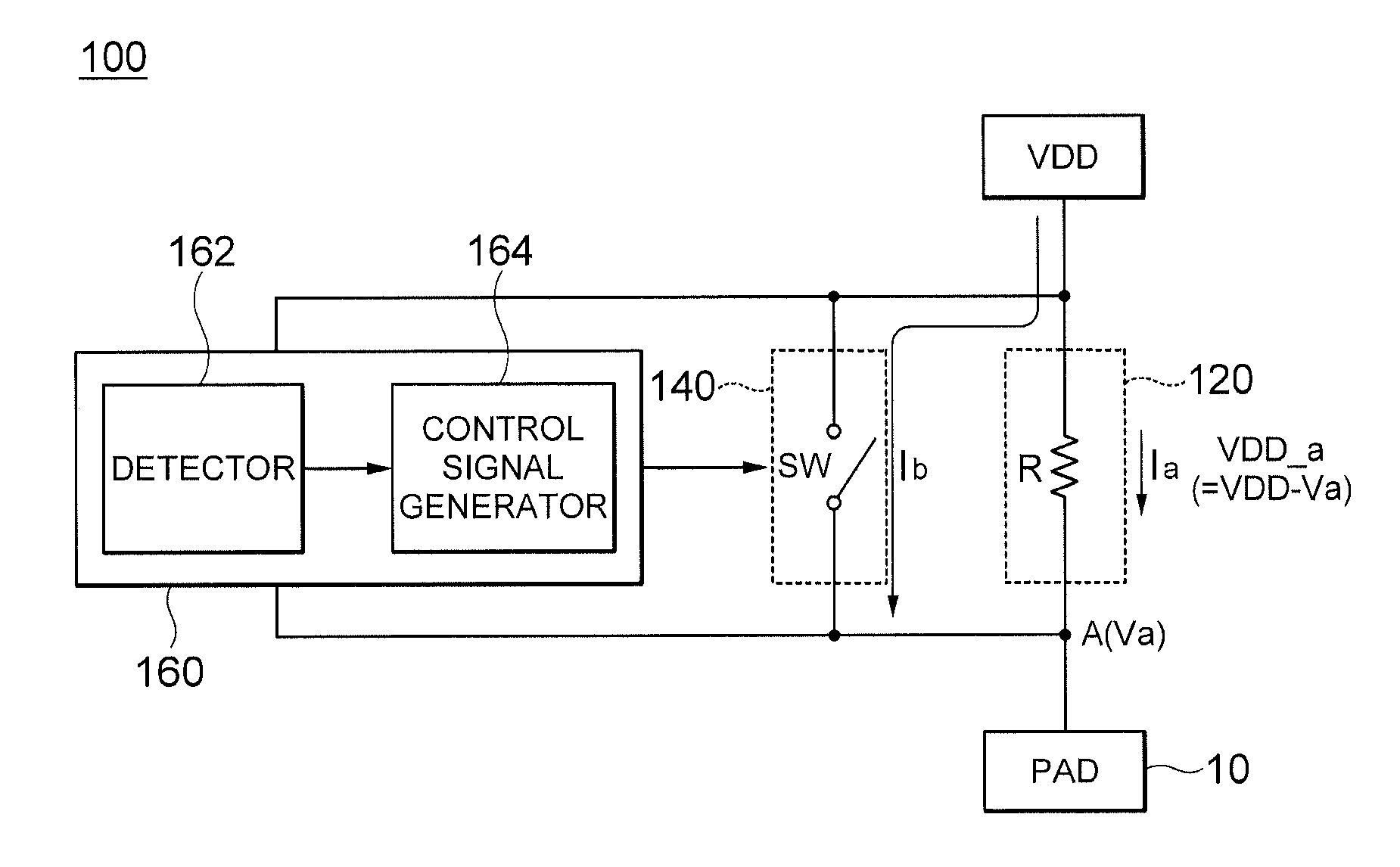
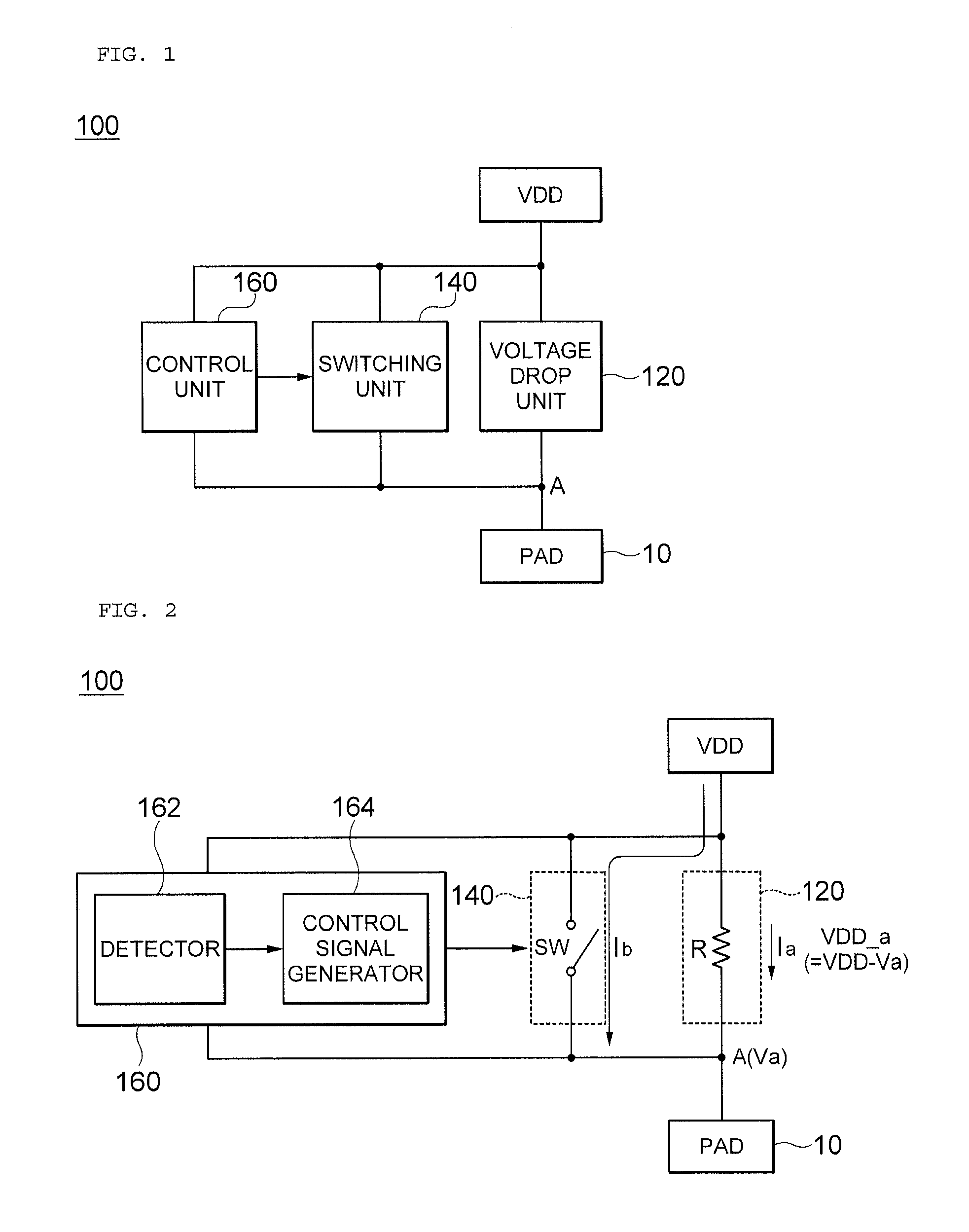
Disclosed herein is a pad controlling apparatus controlling current and voltage applied to a pad, the pad controlling apparatus including: a voltage drop unit dropping the voltage applied to the pad; a switching unit connected in parallel with the voltage drop unit; and a control unit comparing a level of the dropped voltage and first reference voltage with each other and turning on the switching unit on when the level of the dropped voltage is larger than the first reference voltage. According to the present invention, even though interrupt occurs from the outside, a chip may be normally operated.

Description

CROSS REFERENCE(S) TO RELATED APPLICATIONS[0001]This application claims the benefit under 35 U.S.C. Section 119 of Korean Patent Application Serial No. 10-2011-0037294, entitled “Pad Controlling Apparatus” filed on Apr. 21, 2011, which is hereby incorporated by reference in its entirety into this application.BACKGROUND OF THE INVENTION[0002]1. Technical Field[0003]The present invention relates to a pad controlling apparatus, and more particularly, to a pad controlling apparatus for controlling a current and a voltage applied to a pad.[0004]2. Description of the Related Art[0005]Recently, research into a technology of using one battery for a long period of time has been actively conducted. In order to use the battery having limited capacity for a long period of time, the capacity of the battery should be increased and power consumption generated from a device itself should be decreased.[0006]A scheme of allowing unnecessary devices to be maintained in a standby state without being op...

Claims


Application Information

Patent Timeline
Patent Type & Authority Patents(United States)
IPC IPC(8): G05F1/10
CPCG06F1/32G05F1/565G05F1/10
Inventor KWON, YONG ILCHO, HAN JINPARK, TAH JOONCHO, KOON SHIK
Owner SAMSUNG ELECTRO MECHANICS CO LTD
Learn More