Simulated bone or tissue manipulation

a bone or tissue manipulation and simulation technology, applied in the field of orthopaedics, can solve the problems of difficult use in the operating room, high cost and cumbersome equipment, and the most difficult part of fracture reduction, so as to improve the accuracy of bone or tissue manipulation

Active Publication Date: 2013-10-22
DEPUY SYNTHES PROD INC
View PDF112 Cites 23 Cited by
  • Summary
  • Abstract
  • Description
  • Claims
  • Application Information

AI Technical Summary

Benefits of technology

[0007]The present invention is directed to a system and method for performing tissue, and more specifically bone, manipulation. The system and method seeks to improve the accuracy of bone or tissue manipulation and enable surgeons and / or doctors to verify that the desired pre-operative plan for the patient is being achieved.

Problems solved by technology

Fracture reduction may be the most difficult part of the bone fracture fixation procedure.
Drawbacks associated with these technologies are the expense and cumbersome nature of the equipment required to use them.
Their use in the operating room is particularly challenging because the operating room is generally a very restrictive environment.
Operating rooms often lack the necessary space for large equipment and working around the sterile field poses many constraints on freedom to use equipment.

Method used


Image

  • Simulated bone or tissue manipulation
  • Simulated bone or tissue manipulation
  • Simulated bone or tissue manipulation

Examples


Embodiment Construction

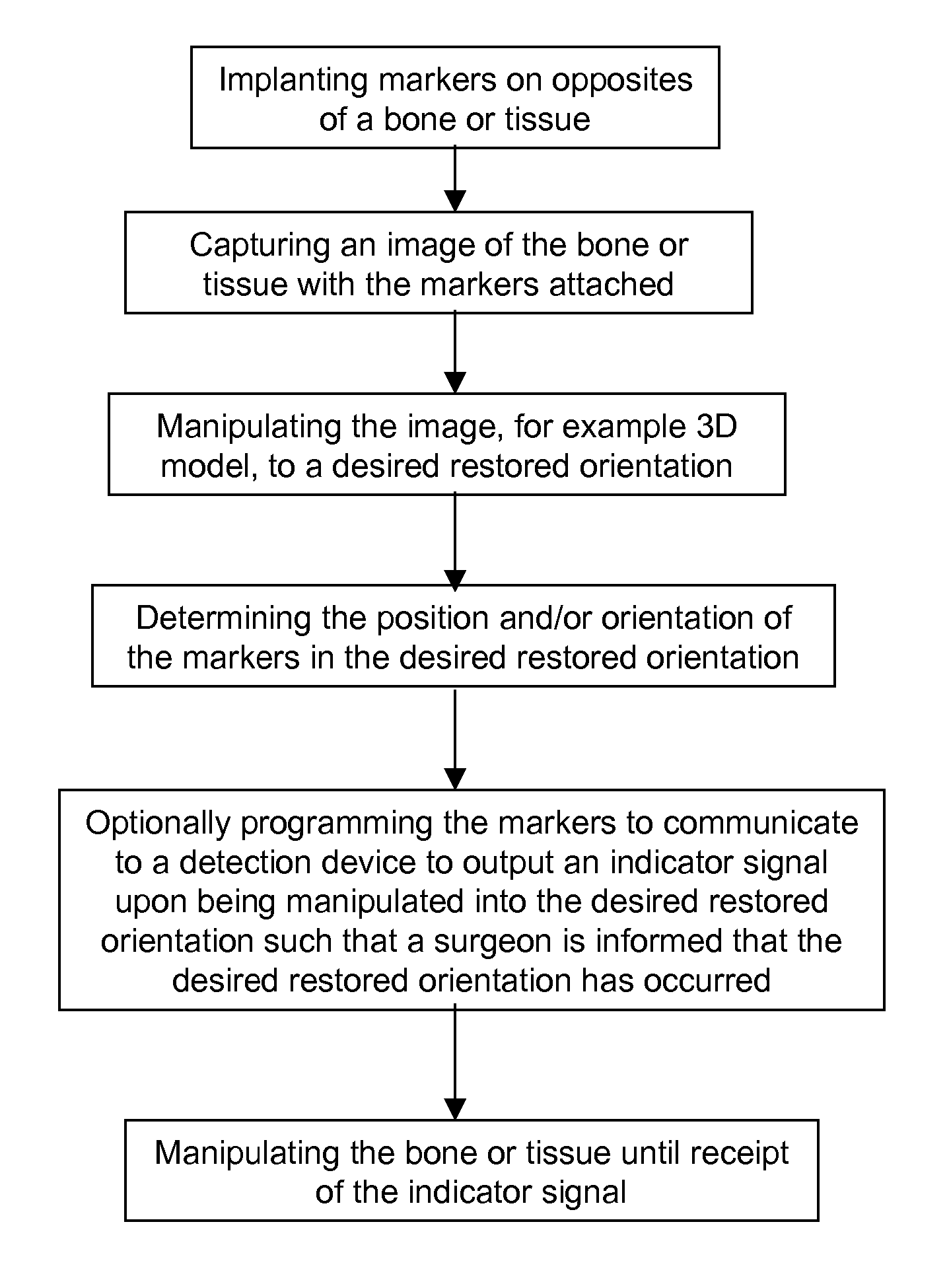
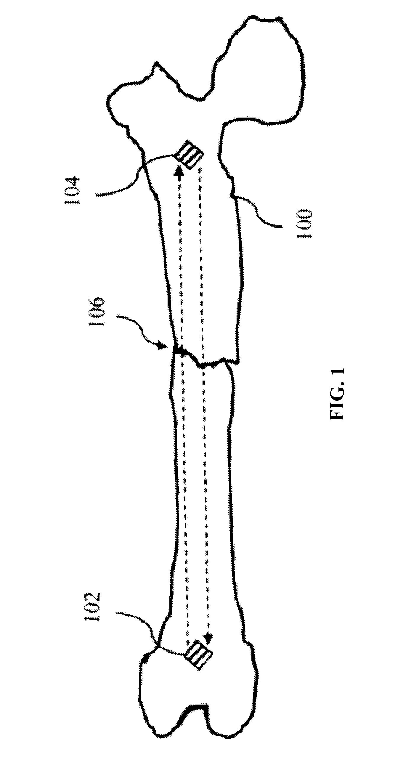
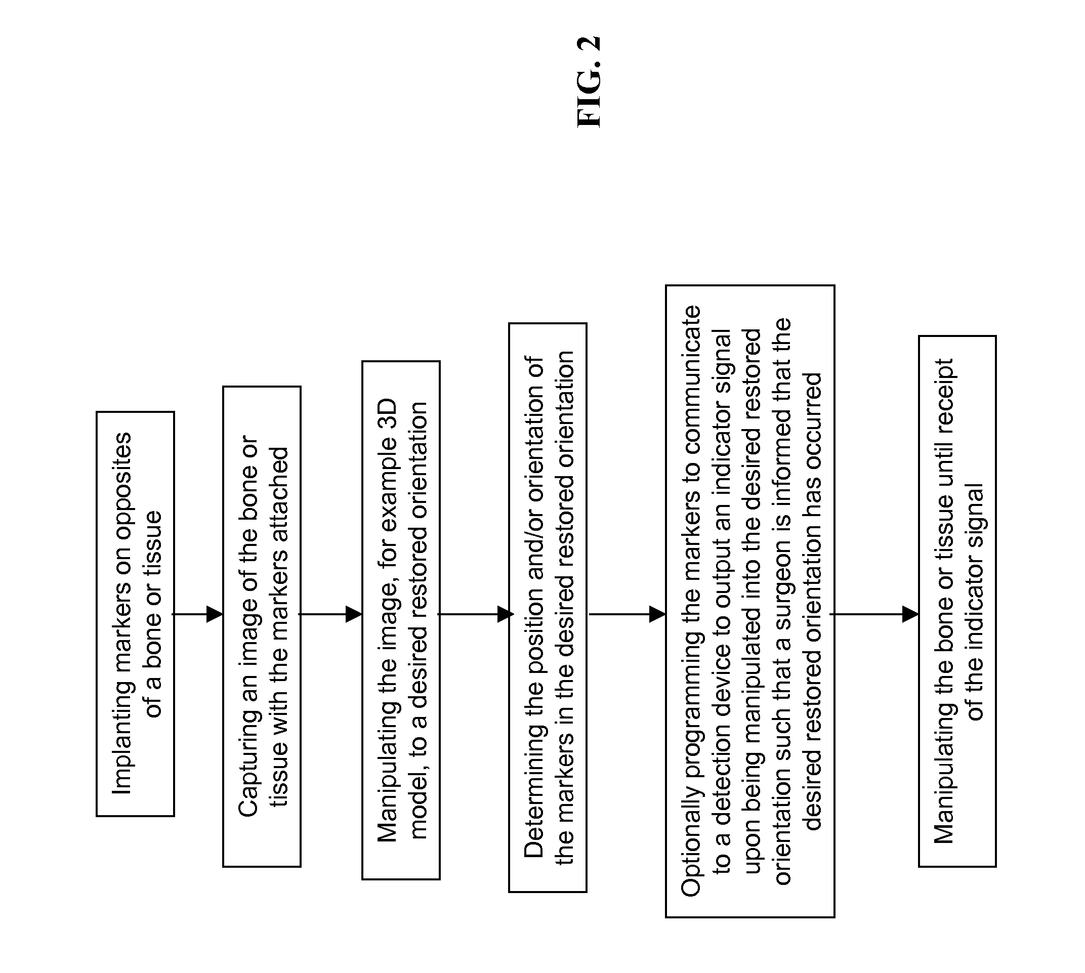
[0040]Certain exemplary embodiments of the invention will now be described with reference to the drawings. In general, such embodiments relate to an apparatus, system and / or method for performing and optionally verifying tissue, preferably bone, manipulation.

[0041]While the system and method of the present invention may be generally described as, generally shown as and may generally be used in connection with fracture fixation, it should be understood that the system and / or method for performing bone or tissue manipulation is not limited in use to repairing bone fractures. Rather, the system and / or method for performing bone or tissue manipulation may be used for manipulating bone, manipulating tissue, manipulating bone fragments caused by, for example, injury, deformation, degeneration, disease, etc. The system and / or method for performing bone or tissue manipulation is not limited to any particular type of fracture and, in fact, may be used even where no fracture exists. The syste...


PUM


Abstract

The present invention is directed to a system and method for performing tissue, preferably bone tissue manipulation. The system and method may include implanting markers on opposite sides of a bone, fractured bone or tissue to facilitate bone or tissue manipulation, preferably in-situ closed fracture reduction. The markers are preferably configured to be detected by one or more devices, such as, for example, a detection device so that the detection device can determine the relative relationship of the markers. The markers may also be capable of transmitting and receiving signals. An image may be captured of the bone or tissue and the attached markers. From the captured image, the orientation of each marker relative to the bone fragment may be determined. Next, the captured image may be manipulated in a virtual or simulated environment until a desired restored orientation has been achieved. The orientation of the markers in the desired restored orientation may then be determined. The desired relationship between markers may then be programmed into, for example, the detection device. Next, actual physical reduction and / or manipulation of the bone may begin. During the manipulation procedure, the orientation of the markers may be continuously monitored and when the markers substantially align with the virtual or simulated orientation of the markers in the desired restored orientation, an indicator signal is transmitted.

Description

CROSS REFERENCE TO RELATED APPLICATION[0001]This application claims priority to U.S. provisional patent application Ser. No. 60 / 837,193, filed Aug. 11, 2006, the contents of which is hereby incorporated by reference in its entirety.FIELD OF THE INVENTION[0002]The invention relates generally to orthopedics. More specifically, the invention relates to a system and method of performing bone or tissue manipulation.BACKGROUND OF THE INVENTION[0003]During an operation for bone fracture fixation, proper reduction (e.g. alignment) of the fracture prior to placement of any fixation devices and / or implants affects restoration of the patient's biomechanical function. Fracture reduction may be the most difficult part of the bone fracture fixation procedure. In addition, as techniques for minimally invasive fracture repair have developed, more surgeons are performing closed fracture reduction (e.g. a procedure for setting a fractured bone without making a skin incision at the fracture site).[000...

Claims


Application Information

Patent Timeline
Patent Type & Authority Patents(United States)
IPC IPC(8): A61B5/05
CPCA61B19/52A61B19/54G06F19/3437G01R33/285A61C19/04A61B17/88A61B8/52A61B8/0841G01R33/5608A61B6/032A61B5/7405A61B5/4836A61B5/055A61B6/52A61B19/50A61B2090/3983A61B90/36A61B2034/2063A61B2090/3912A61B34/20A61B34/10A61B2090/374A61B2090/3762A61B90/39A61B2090/3929A61B2090/3958A61B2090/3966A61B2090/3987G16H50/50A61B5/0036
Inventor FRIGG, ROBERTWEIKEL, STUARTSCHWER, STEFANFLEXNER, GEOFFREYHAMEL, ROSS JONATHAN
Owner DEPUY SYNTHES PROD INC
Why Eureka
Try Eureka