Steer-by-wire steering device

a steering device and wire technology, applied in the direction of power steering, fluid steering, vehicle components, etc., can solve the problem of difficult to achieve the assured engagement of the spline teeth with the spline grooves in a matter of seconds, and achieve the effect of increasing the torque capacity of the power transmission

Inactive Publication Date: 2013-10-29
NTN CORP
View PDF10 Cites 5 Cited by
  • Summary
  • Abstract
  • Description
  • Claims
  • Application Information

AI Technical Summary

Benefits of technology

[0013]According to the above described construction, since the switching operation of selectively connecting and disconnecting the input member with and from the output member is performed by the use of the clutch mechanism operable to selectively engage and disengage the clutch rolling element with and from the clutch groove, when the phase of the clutch rolling element and the phase of the clutch groove are matched with each other, the clutch rolling element engages with the clutch groove. Since there is no need to align the phase during the switching operation, the switching operation can be performed assuredly and in a reduced time.
[0016]According to the above described construction, separate from the turning motor and the tuning power transmitting mechanism for transmitting the power from the turning motor to the steering shaft, the provision is made of the toe angle adjusting motor and the toe angle adjusting power transmitting mechanism for transmitting the power from the toe angle adjusting motor to the steering shaft to perform the toe angle adjustment. Therefore, in the event of failure of the turning motor, the power of the toe angle adjusting motor is transmitted by the clutch mechanism of the changeover unit to the turning power transmitting mechanism to perform the turning by means of the toe angle adjusting motor. For this reason, even in the event of failure of the turning motor used to turn the vehicle wheel, the turning can be performed by the utilization of the toe angle adjusting motor as a drive source for the turning. Also, even when the turning motor is normally operating, the toe angle adjusting motor functions as a drive source for adjusting the toe angles of the vehicle wheels, and, therefore, it can be an economical structure as compared with the conventional case in which an auxiliary motor that is activated only in the event of failure of the turning motor is employed.
[0022]In the present invention, the clutch groove may have a groove bottom surface at one end adjoining the non-grooved surface or adjoining the raceway ring peripheral surface of the bearing, which bottom surface at one end may be rendered to be a tapered surface gently inclined towards the non-grooved surface or the raceway ring peripheral surface of the bearing. Where the groove bottom surface at that end of the clutch groove is rendered to be the tapered surface in this way, the selective engagement and disengagement of the clutch rolling element relative to the clutch groove can be accomplished smoothly.
[0024]In the present invention, a position of installation of the clutch rolling element may be a plurality of positions adjoining to each other in an axial direction. Where the position of installation of the clutch rolling element is chosen to be the plurality of the positions in this way, the torque capacity of the power transmission can be increased.

Problems solved by technology

Also, even where the use of the tapered elements are employed at the ends of in the spline teeth and the spline grooves as the phase guide elements, it has been difficult to accomplish the assured engagement of the spline teeth with the spline grooves quickly in a matter of seconds.

Method used


Image

  • Steer-by-wire steering device
  • Steer-by-wire steering device
  • Steer-by-wire steering device

Examples


Embodiment Construction

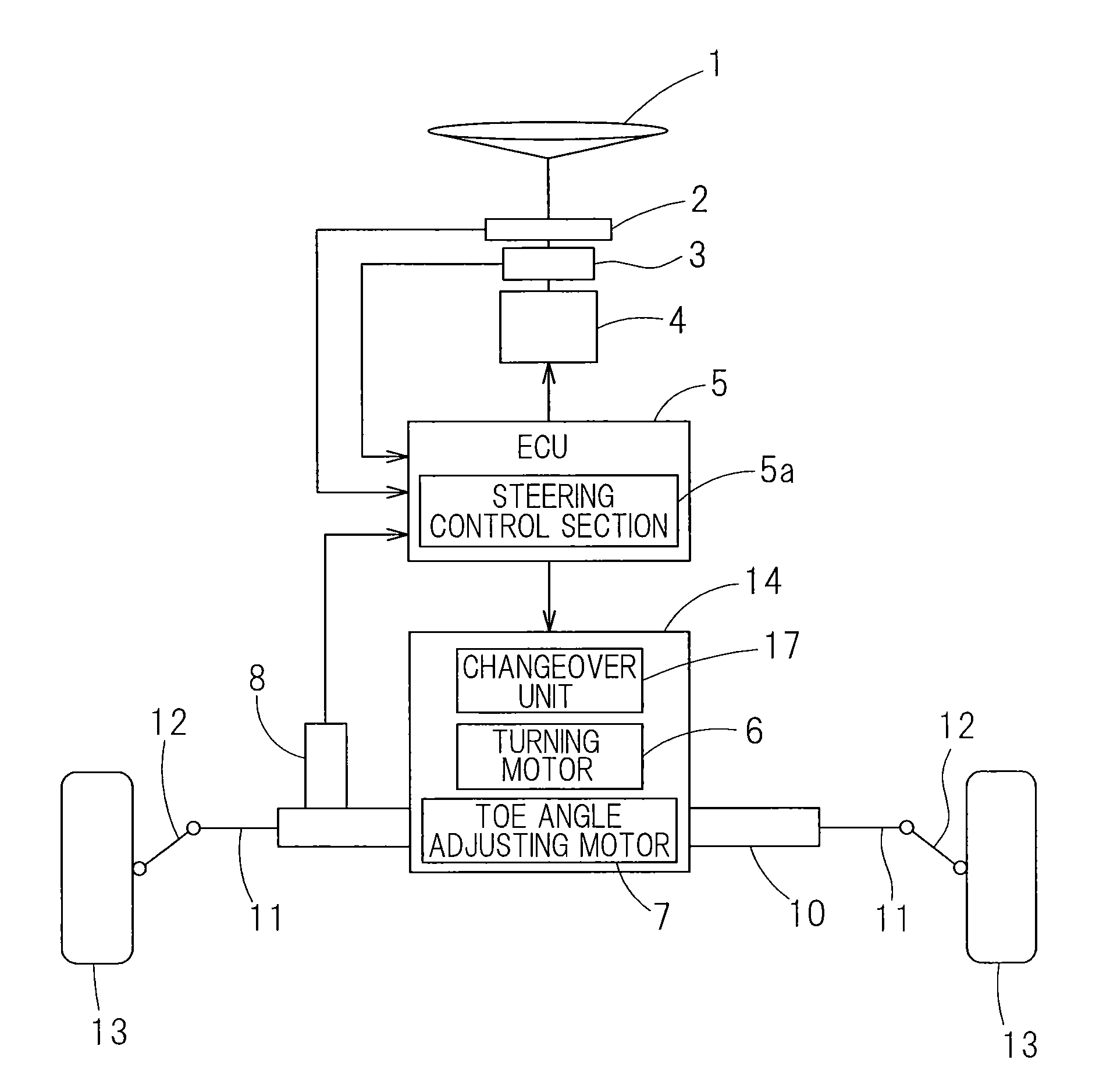
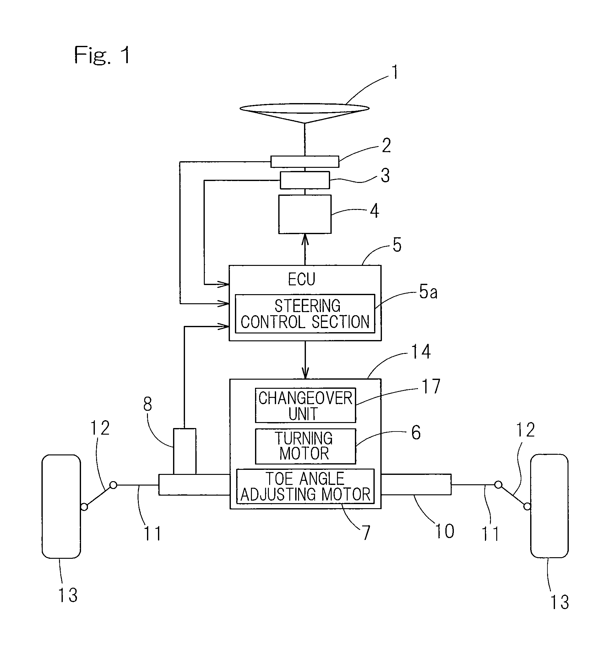
[0041]A first embodiment of the present invention will be described in detail with reference to the accompanying drawings. A steer-by-wire steering device includes, as shown in FIG. 1 in a schematic representation, a steering wheel 1 adapted to be steered by a vehicle driver, a steering angle sensor 2, a steering torque sensor 3, a steering reactive force motor 4, a steering axle 10 movable in a direction axially thereof for wheel turning and coupled with left and right vehicle wheels 13 through corresponding knuckle arms 12 and tie rods 11, a steering axle drive unit 14 for driving the steering axle 10, a turning angle sensor 8, and an ECU (Electric Control Unit) 5 including a steering control section 5a. The ECU 5 and its steering control section 5a are constituted by an electronic circuit or the like including a microcomputer and its software control program.

[0042]The steering wheel 1 is not mechanically connected with the steering axle 10 for wheel turning purpose. To the steeri...


PUM


Abstract

A steer-by-wire steering device includes a steering wheel connected with a steering shaft, a steering angle sensor, a steering reactive force motor, and a steering control unit for controlling a steering shaft drive motor and the steering reactive force motor. Provided is a power transmitting mechanism for transmitting the power from the steering shaft drive motor to the steering shaft. A changeover unit for selectively connecting and disconnecting the power is disposed on the way thereof. The changeover unit includes a clutch mechanism comprised of an input member and an output member juxtaposed in an axial direction for movement in the axial direction and, also, rotatable relative to each other, a clutch groove provided in one of those members, and a clutch rolling element provided in the other of those members and biased in a radial direction by the clutch groove so that it can be selectively engaged and disengaged.

Description

CROSS REFERENCE TO THE RELATED APPLICATION[0001]This application is a U.S. National Phase application of PCT / JP2011 / 060624 filed May 9, 2011 and claims the non benefit of Japanese Application No. 2010-110936 filed May 13, 2010 in the Japanese Intellectual Property Office, the contents of both of which are incorporated herein by reference.BACKGROUND OF THE INVENTION[0002]1. (Field of the Invention)[0003]The present invention relates to a steer-by-wire steering device of a kind, in which steering is accomplished by means of steering wheel that is not mechanically coupled with a steering axle for wheel turning purpose.[0004]2. Description of Related Art[0005]In this type of the steer-by-wire steering device, the arrangement has been suggested in which by moving a shaft member having a spline in an axial direction, transmission of a power in a power transmitting mechanism is switched (see the patent document 1 listed below). In the case of a splined engagement mechanism according to thi...

Claims


Application Information

Patent Timeline
Patent Type & Authority Patents(United States)
IPC IPC(8): B62D5/02
CPCB62D5/001B62D5/043B62D5/006B62D6/008
Inventor SUGAI, TOMOHIRO
Owner NTN CORP
Why Eureka
Try Eureka