Load driving device including first and second electric power lines between power supply and electric power conversion device

a technology of a driving device and a power supply, which is applied in the direction of electric devices, communication cables, and totally enclosed bus-bar installations, to achieve the effects of high inductance value, high inductance value, and increased flux interlinkag

Inactive Publication Date: 2012-09-11
TOYOTA JIDOSHA KK
View PDF28 Cites 3 Cited by
  • Summary
  • Abstract
  • Description
  • Claims
  • Application Information

AI Technical Summary

Benefits of technology

[0008]According to the load driving device described above, the first and second electric power lines are placed such that an inductance that is structurally present in a circular path configured with the power supply, the first and second electric power lines, and the electric power conversion device has an increased value, when compared to that in a cabling structure generally established based on the positional relationship between the power supply and the electric power conversion device. Thereby, the first and second electric power lines can be configured to have high inductance values, and thus the power supply has an apparent high impedance, allowing a ripple current, superimposed on a DC current flowing through the power supply when a switching operation is performed in the electric power conversion device, to be decreased. Since a required inductance value can be achieved by the cabling structure of the electric power lines on this occasion, vibration noise from the power supply can be suppressed.
[0027]According to the present invention, by configuring electric power lines connecting a power supply and a driving device to have high inductance values using a cabling structure, a ripple current superimposed on a DC current flowing through the power supply when a switching operation is performed in the driving device can be decreased. As a result, vibration noise in the power supply can be suppressed.

Problems solved by technology

Due to the ripple current, a vibration occurs in a battery, which may cause noise.

Method used


Image

  • Load driving device including first and second electric power lines between power supply and electric power conversion device
  • Load driving device including first and second electric power lines between power supply and electric power conversion device
  • Load driving device including first and second electric power lines between power supply and electric power conversion device

Examples


first embodiment

[0041][First Embodiment]

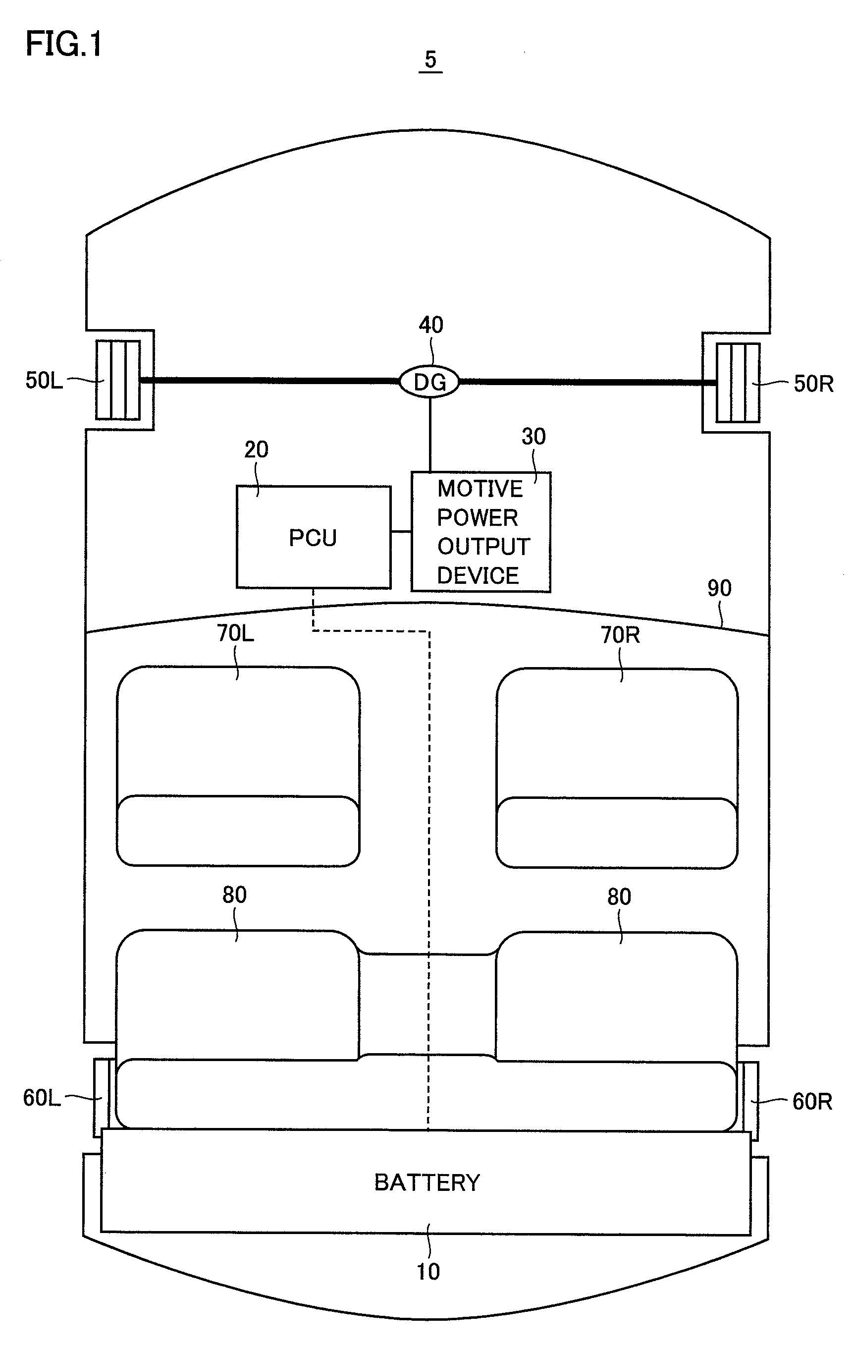
[0042]FIG. 1 is a schematic block diagram showing an entire configuration of a hybrid vehicle illustrated as an example to which a load driving device in accordance with the present invention is mounted.

[0043]Referring to FIG. 1, a hybrid vehicle 5 includes a battery 10, a PCU (Power Control Unit) 20, a motive power output device 30, a differential gear (DG) 40, front wheels 50L and 50R, rear wheels 60L and 60R, front seats 70L and 70R, and a rear seat 80.

[0044]Battery 10 is disposed behind rear seat 80. Battery 10 is electrically connected to PCU 20. PCU 20 is disposed, for example, using a region below front seats 70L and 70R, that is, a region below a floor. Motive power output device 30 is disposed at an engine room located in front of a dashboard 90. PCU 20 is electrically connected to motive power output device 30. Motive power output device 30 is coupled to DG 40.

[0045]Battery 10, which is a DC power supply, is formed for example of a secondary battery...

second embodiment

[0120][Second Embodiment]

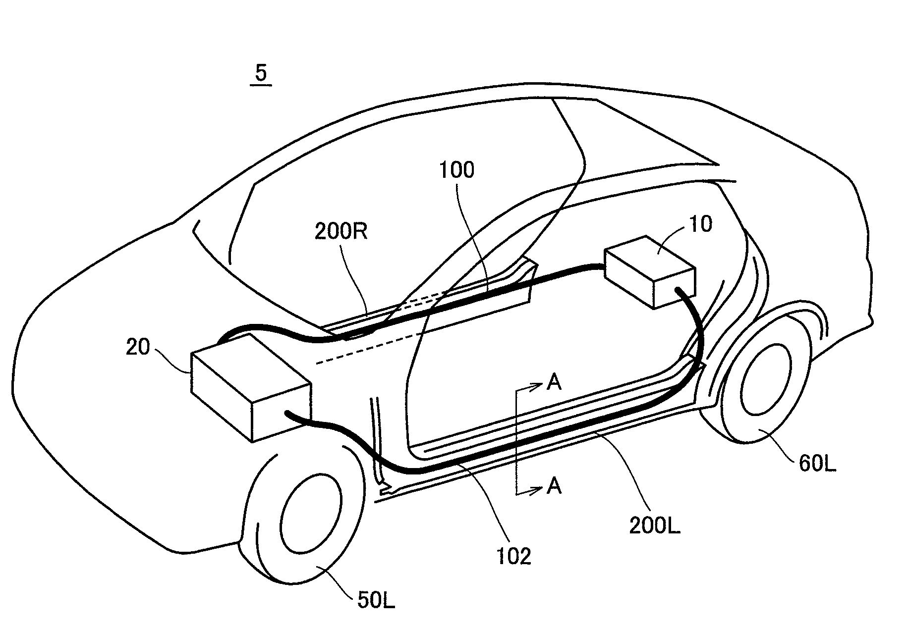
[0121]FIG. 11 is a perspective view of hybrid vehicle 5 to which a cabling structure of the electric power cables in accordance with a second embodiment of the present invention is applied.

[0122]Referring to FIG. 11, in hybrid vehicle 5, rocker outer reinforcement 200L and a door belt line reinforcement 400 forming a portion of the vehicle left side surface in the vehicle width direction extend in the vehicle front-rear direction. Rocker outer reinforcement 200L and door belt line reinforcement 400 constitute vehicle left side frame members.

[0123]In such a vehicle body structure, electric power cable 102 is provided such that a portion thereof along the vehicle front-rear direction is placed along the inner side surface of rocker outer reinforcement 200L in the vehicle width direction. As described in FIG. 8, the portion of electric power cable 102 is placed in the space portion formed between the inner side surface of rocker outer reinforcement 200L in the ...


PUM


Abstract

In a hybrid vehicle, rocker outer reinforcements serving as vehicle side frame members in a vehicle width direction extend in a vehicle front-rear direction. An electric power cable is provided such that a portion thereof along the vehicle front-rear direction is placed along an inner side surface of the rocker outer reinforcement in the vehicle width direction. An electric power cable is provided such that a portion thereof along the vehicle front-rear direction is placed along an inner side surface of the rocker outer reinforcement in the vehicle width direction. Further, each of the electric power cables is placed in a space portion formed between the rocker outer reinforcement and a center body pillar serving as an energy absorbing member absorbing energy in the event of a side collision of the vehicle.

Description

TECHNICAL FIELD[0001]The present invention relates to a load driving device, and more particular to a load driving device configured to include a switching element and receiving electric power from a battery to drive an electric load.BACKGROUND ART[0002]Japanese Patent Laying-Open No. 10-066383 discloses a drive control device for a permanent magnet synchronous motor (PM motor). The drive control device includes a boost circuit boosting a battery voltage prior to be supplied to an electric power converter and in response to a command, and means for causing the boost circuit to perform a boost operation such that a boosted voltage value is higher than a voltage on a DC (direct current) terminal side of the electric power converter that is required to achieve a target operation point of the PM motor.[0003]In the drive control device, when the target operation point of the PM motor is located at a higher rotation side than an outputtable range with the present battery voltage, the batt...

Claims


Application Information

Patent Timeline
Patent Type & Authority Patents(United States)
IPC IPC(8): B60L1/00B60L3/00H02G3/00
CPCB60L3/0046B60L3/0053B60R16/0215B60L2200/26Y02T90/34B60L58/30B60L58/10Y02T90/40Y02T10/70
Inventor YOSHINAGA, FUMITAKATAKAMATSU, NAOYOSHI
Owner TOYOTA JIDOSHA KK
Why Eureka
Try Eureka