Method for planning and/or configuring a project

a technology for planning and/or configuration and project, applied in the direction of programme control, electric controllers, total factory control, etc., can solve the problems of long response time, substantial performance problems, and easy errors in steps, so as to improve the planning and/or configuration of the project, and simplify the method of planning and/or configuration

Inactive Publication Date: 2008-02-26
SIEMENS AG
View PDF5 Cites 3 Cited by
  • Summary
  • Abstract
  • Description
  • Claims
  • Application Information

AI Technical Summary

Benefits of technology

[0004]One object of the present invention is to simplify a method for planning and / or configuring a project. A further object of the invention is to provide an engineering system that improves the planning and / or configuration of a project.SUMMARY OF THE INVENTION
[0010]It is advantageous that the project data themselves are not centrally stored but only the data records that indicate to the programming units which partial project data are stored on which programming units. As a result, the project data can be handled more easily. If, for example, a programming unit requires partial project data of another programming unit, this programming unit accesses the data of the other programming unit directly.
[0011]Due to the distribution and thus, decentralization of the project data, in contrast to the central data management as practiced in the related art, performance during simultaneous planning in a multi-user operation is dramatically improved because a large part of the data relevant for local planning is also stored on the local programming unit of the corresponding user. The relevant and locally stored project data can thus be accessed very quickly, without multi-user conflicts, without bottlenecks in the computer network and without losing access to the total project data. As a result, the performance in the multi-user operation is usually almost identical to the performance in a single user operation. Furthermore, the integration of partial project data in the total project is no longer required. Data matching and consistency or plausibility checks of the data of the programming units involved in the total project can be done directly via the network. The time required to match the data of the programming units involved in the project is thereby also reduced significantly. Furthermore, the decentralized project data management simplifies error handling. Any errors that occur in the planning and / or configuration phase do not “jeopardize” the data of the total project but only partial project data. Such errors are easy to locate and are analyzed and corrected by the programming unit that is handling the partial project containing the errors. In addition, decentralized project data management makes it easy to handle new versions of partial project data, which can be easily integrated into the total project.

Problems solved by technology

Because the project data are centrally stored, they can be very voluminous depending on the complexity of the automation device.
Furthermore, during planning in a so-called multi-user operation, particularly if many designers simultaneously compete for access to the centrally stored project data via the network, substantial performance problems and long response times may occur.
These planning steps are prone to errors, and the handling of the data and subsequent correction of the total project data is labor intensive.
Furthermore, matching the engineering data of the automation systems, the control and monitoring systems, and the batch systems can only be done in the context of the total project data.
This matching is usually very time consuming and involves a project-wide interruption of the planning work.

Method used


Image

  • Method for planning and/or configuring a project
  • Method for planning and/or configuring a project
  • Method for planning and/or configuring a project

Examples


Embodiment Construction

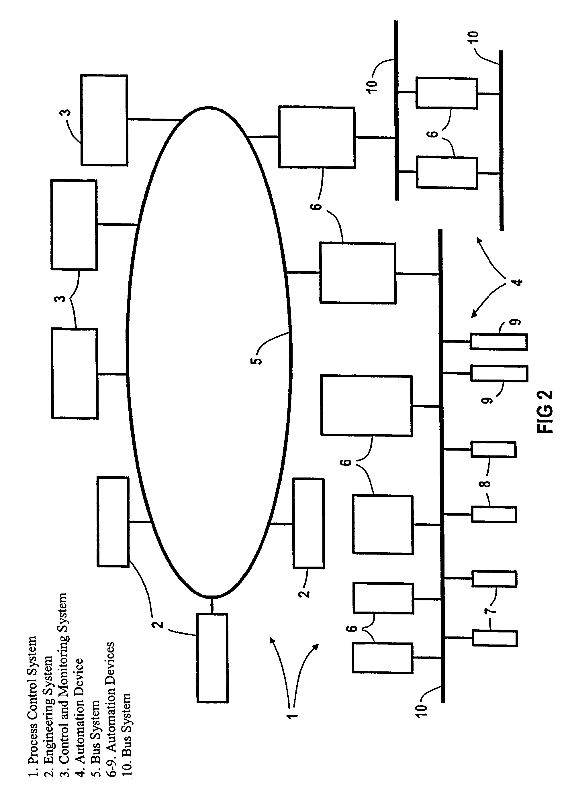
[0017]Reference is first made to FIG. 2, which shows a process control system 1. The process control system 1 has an engineering system 2, a control and monitoring system 3, and a planned and configured automation device 4. The engineering system 2 is provided for planning and / or configuring the automation device 4. The automation device 4, which is connected to the engineering system 2 and the control and monitoring system 3 by a bus system 5 and bus connections (not depicted), includes various automation devices 6, actuators 7, sensors 8 and other automation components 9 required to control a technical installation.

[0018]The automation devices 6, which are interconnected by the bus system 5 and / or other suitable bus systems 10, can have different configurations. For example, ordinary automation devices for solving small, medium-sized and larger automation tasks are provided within the automation device 4. As a non-limiting example, programmable micro-controllers can be used to sol...


PUM


Abstract

A method for at least one of planning and configuring a project, which represents an automation device (4) for controlling a technical installation. The project data required for the at least one of planning and configuring the automation device (4) can be stored in an engineering system (2). The at least one of planning and configuring of the project is simplified by subdividing the project into a number of partial projects (Tp1, . . . ). The partial projects (Tp1, . . . ) are at least one of planned and configured on different programming units (13, . . . ) that are interconnected. Data records (18a, . . . ) are centrally stored that indicate which partial projects (Tp1, . . . ) are actively connected to which programming units (13, . . . ). These data records (18a, . . . ) can be read out by the programming units (13, . . . ).

Description

[0001]This is a Continuation of International Application PCT / DE03 / 00610, with an international filing date of Feb. 25, 2003, which was published under PCT Article 21(2) in German, and the disclosure of which is incorporated into this application by reference.FIELD AND BACKGROUND OF THE INVENTION[0002]The invention relates to a method for planning and / or configuring a project, which includes an automation device to control a technical installation. The project data required for planning and / or configuring the installation is stored in an engineering system. The invention further relates to an engineering system for planning and / or configuring a project.[0003]Such a method is known in the related art from Siemens catalog ST PCS 7, chapter 1, issue 2001. A process control system for controlling a technical installation has an engineering system, which is provided, in particular, to configure hardware and / or software components, to design communication networks, to design continuous an...

Claims


Application Information

Patent Timeline
Patent Type & Authority Patents(United States)
IPC IPC(8): G06F17/50G06F9/44G05B11/01G05B15/02G05B19/05G05B19/18G05B19/418G05B19/42G06F7/00G06F17/30G06F19/00
CPCG05B19/056G05B19/41845Y02P90/02
Inventor REUTER, THOMAS
Owner SIEMENS AG
Why Eureka
Try Eureka