
Electrical connections to a microactuator in a hard disk drive suspension

a technology of hard disk drive and electrical connection, which is applied in the direction of instruments, record information storage, and support for heads, can solve the problems of dsa suspension, higher piece count, and increased assembly cost, and achieve the elimination of the expensive tail weave process step, the effect of eliminating the conductive epoxy bonding step

Active Publication Date: 2013-10-29
MAGNECOMP
View PDF18 Cites 51 Cited by
  • Summary
  • Abstract
  • Description
  • Claims
  • Application Information

AI Technical Summary

Benefits of technology

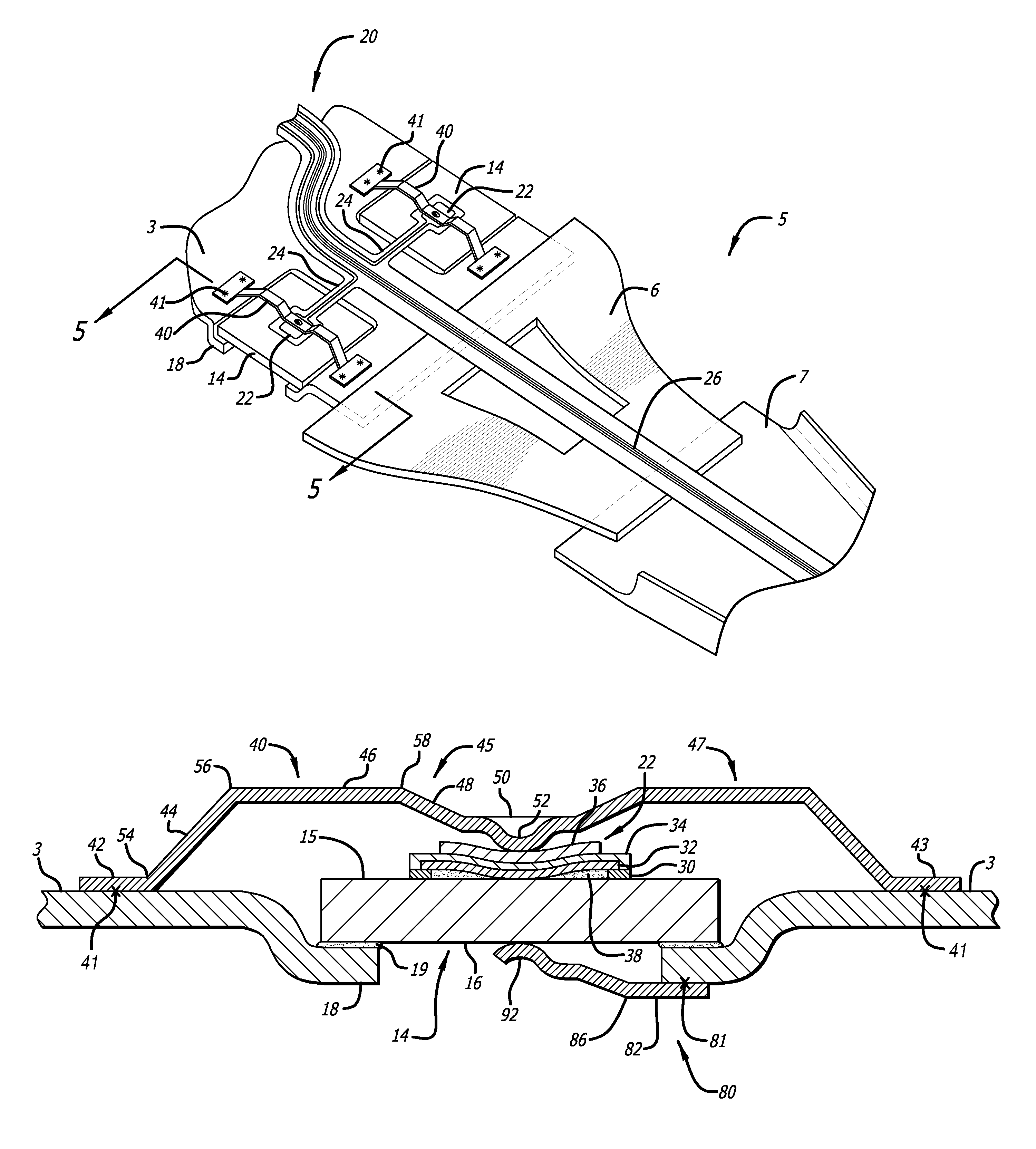
This patent describes a way to improve the connection between a stainless steel piece and a microactuator in a suspension system. A spring finger or resilient dimple is welded onto the stainless steel body of the suspension in the area of the microactuator. This additional piece pushes an electrical contact pad that forms part of the suspension's circuit against the microactuator with sufficient force to maintain electrical contact. The surfaces are coated with gold and a thin layer of electrical contact enhancing and friction reducing material between them. This process can be quickly and easily integrated into existing assembly processes without introducing any new steps. The invention eliminates the expensive tail weave process and reduces the use of conductive epoxy bonding.

Problems solved by technology

DSA suspensions carry the disadvantages, however, of higher piece count and greater assembly costs.
The most expensive additional part used in DSA suspensions is the microactuator itself, which is typically a flat piece of piezoelectric crystal, typically lead zirconate titanate (PZT), and its associated manufacturing challenges.
Such a connection can be time consuming to make and / or requires special bonding equipment.
Additionally, the use of conductive epoxy from the PZT positive electrode to the PZT driving voltage conductor can introduce potentially contaminating epoxy particles into the disk drive assembly process, and presents additional manufacturing complications.
The bonding process also increases process time, and it can be difficult to maintain manufacturing consistency.
Tail weaves are typically constructed using exacting and hence expensive skilled labor.

Method used


Image

  • Electrical connections to a microactuator in a hard disk drive suspension
  • Electrical connections to a microactuator in a hard disk drive suspension
  • Electrical connections to a microactuator in a hard disk drive suspension

Examples


Embodiment Construction

[0023]For discussion purposes, the present disclosure will refer to the microactuator as being a “PZT,” although it will be understood that other types of microactuators could be used as well, and thus the invention is applicable to DSA suspensions using other types of micro actuators.

[0024]According to the invention, electrical connections can be made to the PZT using biased mechanical contacts rather than the previously employed soldered contacts or adhesive contacts.

[0025]FIG. 4 is an oblique view from what will be referred to as the top of the suspension for discussion purposes, of a first embodiment of a DSA suspension having improved PZT electrical contacts according to the present invention. In this view, the PZT elements are shown mounted on stamped tabs 18 within the base plate 3 of a hard disk drive suspension 5. Load beam 7 is connected to base plate 3 by hinges or spring 6. Spring 6 may be a separate piece of stainless steel, or it may be integral with either base plate ...


PUM


Abstract

In a disk drive suspension circuit, an electrical contact from a flexible circuit to a face of a PZT microactuator is provided by a mechanical bias to press a contact pad of the flexible circuit against the PZT surface. The mechanical bias is provided by a piece of stainless steel that is welded to a nearby point or points on the suspension, and which biases the electrical contact pad carrying the PZT driving voltage against the PZT. The piece of stainless steel may be in the form of a flat piece welded on one or more sides of the contact pad, and may include a dimple for pressing against the contact pad. Additional insulation material may be provided between the dimple and the contact pad to prevent the dimple from penetrating through the flexible circuit's cover layer and shorting the driving voltage.

Description

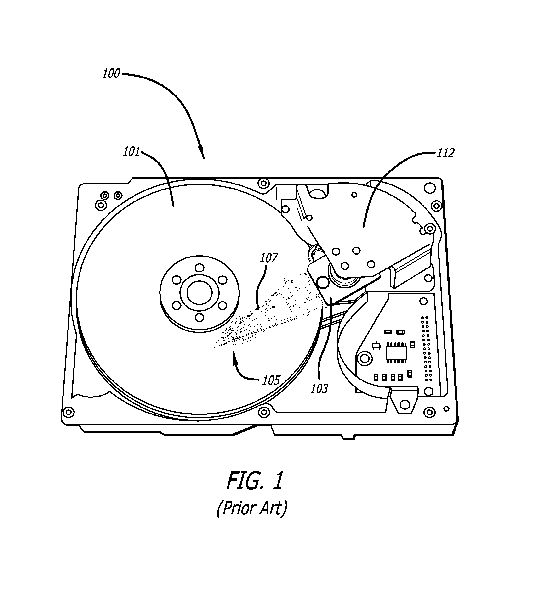
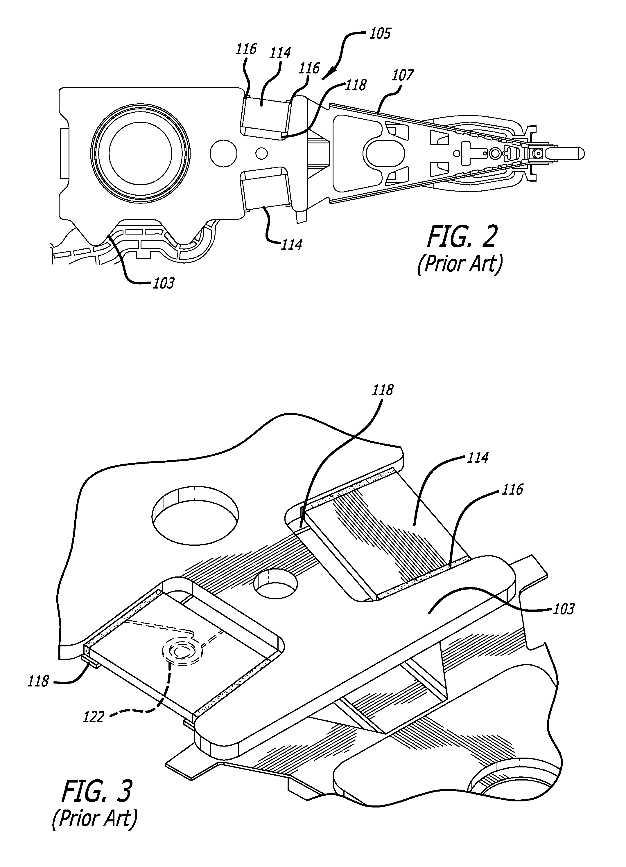
CROSS-REFERENCE TO RELATED APPLICATIONS[0001]This application claims priority from U.S. provisional patent application Ser. No. 61 / 411,357 filed Nov. 8, 2010, which is incorporated by reference as if fully set forth herein.BACKGROUND OF THE INVENTION[0002]1. Field of the Invention[0003]This invention relates to the field of dual stage actuator (DSA) type suspensions for disk drives including hard disk drives. More particularly, this invention relates to the field of electrical connections to microactuators in a hard disk drive suspension, particularly to piezoelectric microactuators.[0004]2. Description of Related Art[0005]Magnetic hard disk drives and other types of spinning media drives such as optical disk drives are well known. FIG. 1 is an oblique view of an exemplary prior art hard disk drive and suspension for which the present invention is applicable. The prior art disk drive unit 100 includes a spinning magnetic disk 101 containing a pattern of magnetic ones and zeroes on i...

Claims


Application Information

Patent Timeline
IPC IPC(8): G11B5/55G11B21/24
CPCG11B5/4873G11B5/482G11B5/486G11B5/483H01L2224/40
Inventor HAHN, PETEREE, KUEN CHEE
Owner MAGNECOMP
Learn More