Mold crucible system for connecting tubes and cables and method thereof

a technology of connecting tubes and crucibles, which is applied in the direction of gas flame welding apparatus, soldering media, soldering auxillary devices, etc., to achieve the effect of reducing the risk of inflammation of volatile components of gas pipelines

Active Publication Date: 2013-11-05
KLK ELECTRO MATERIALES S L U
View PDF18 Cites 1 Cited by
  • Summary
  • Abstract
  • Description
  • Claims
  • Application Information

AI Technical Summary

Benefits of technology

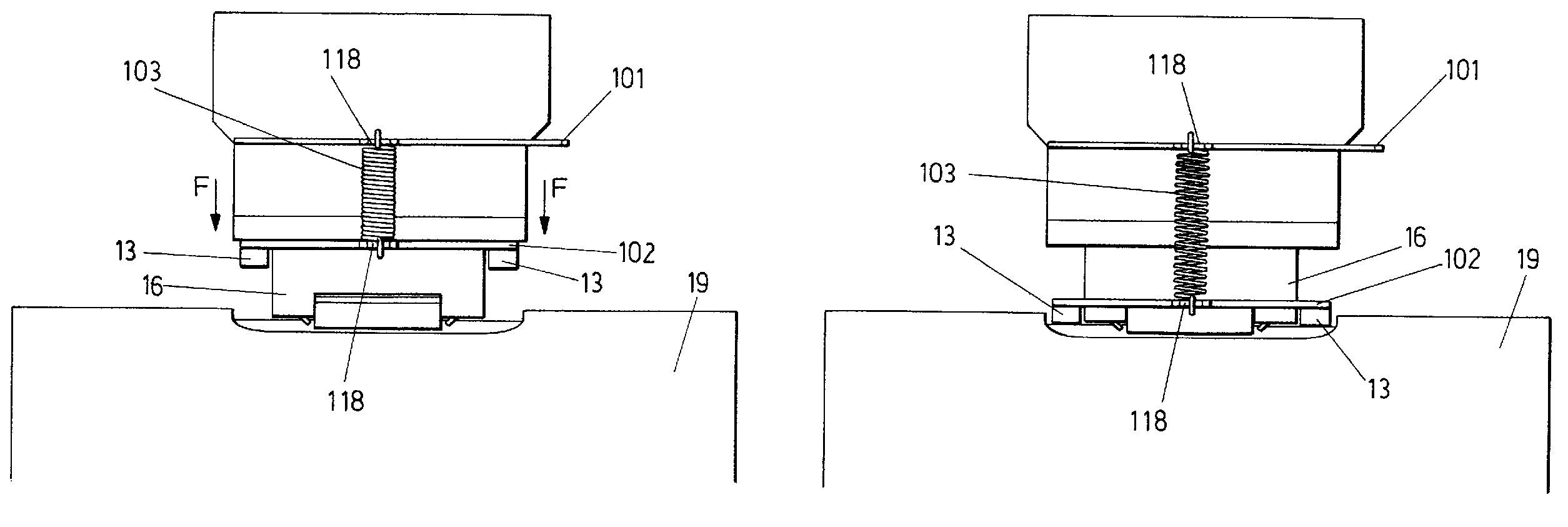
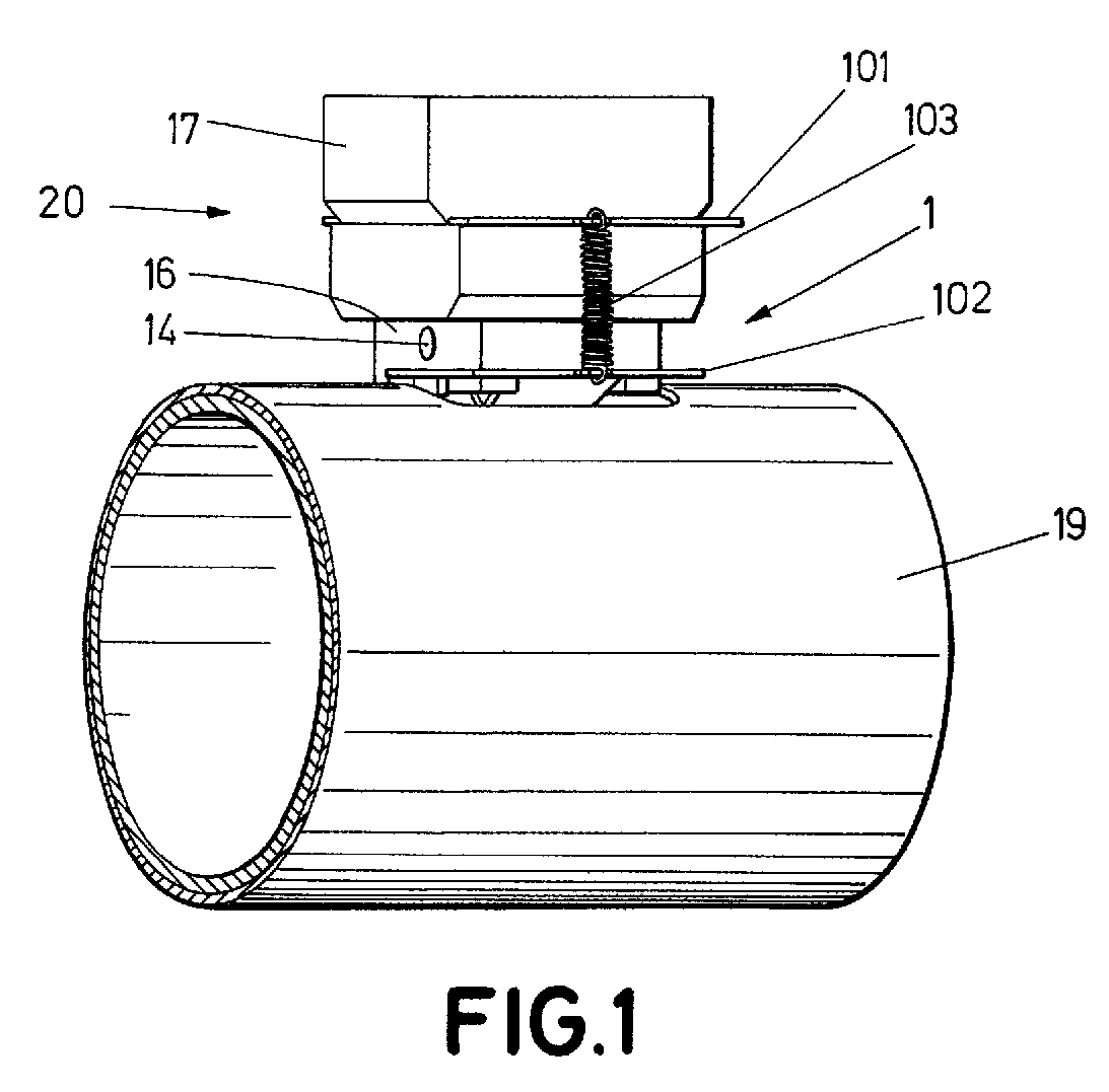
[0011]The system and process of welding object of the invention, like the object of the invention in patent application P201030202, enables to make electric connections between conductive cables of different sections and the surface of steel tubes of different diameters, without the temperature of the tube's surface exceeding a predetermined value. Both have similarities with what was described in the aforementioned utility model, U8702866 since it takes advantage of the heat that is generated in the aluminothermic reaction and it eliminates the possibility of structural changes in the steel, given that they allow for the placement of a small plate between the cable and the area where the welding is to be made. This plate incorporates, on the side in contact with the steel surface, the alloy with a low fusion point. Like in the case above, the heat produced by the aluminothermic reaction will melt the low fusion point alloy so that it will be possible to weld, simultaneously, the aforementioned steel plate and the connection cable to the other side of the plate.
[0015]On the one hand, economically, it is more advantageous when the number of welding to be made is reduced, since it is not necessary to carry out the investment in the anchoring system as described in application P201030202. The fact that, being fully consumable, there are no required maintenance operations on any component might also be an advantage.
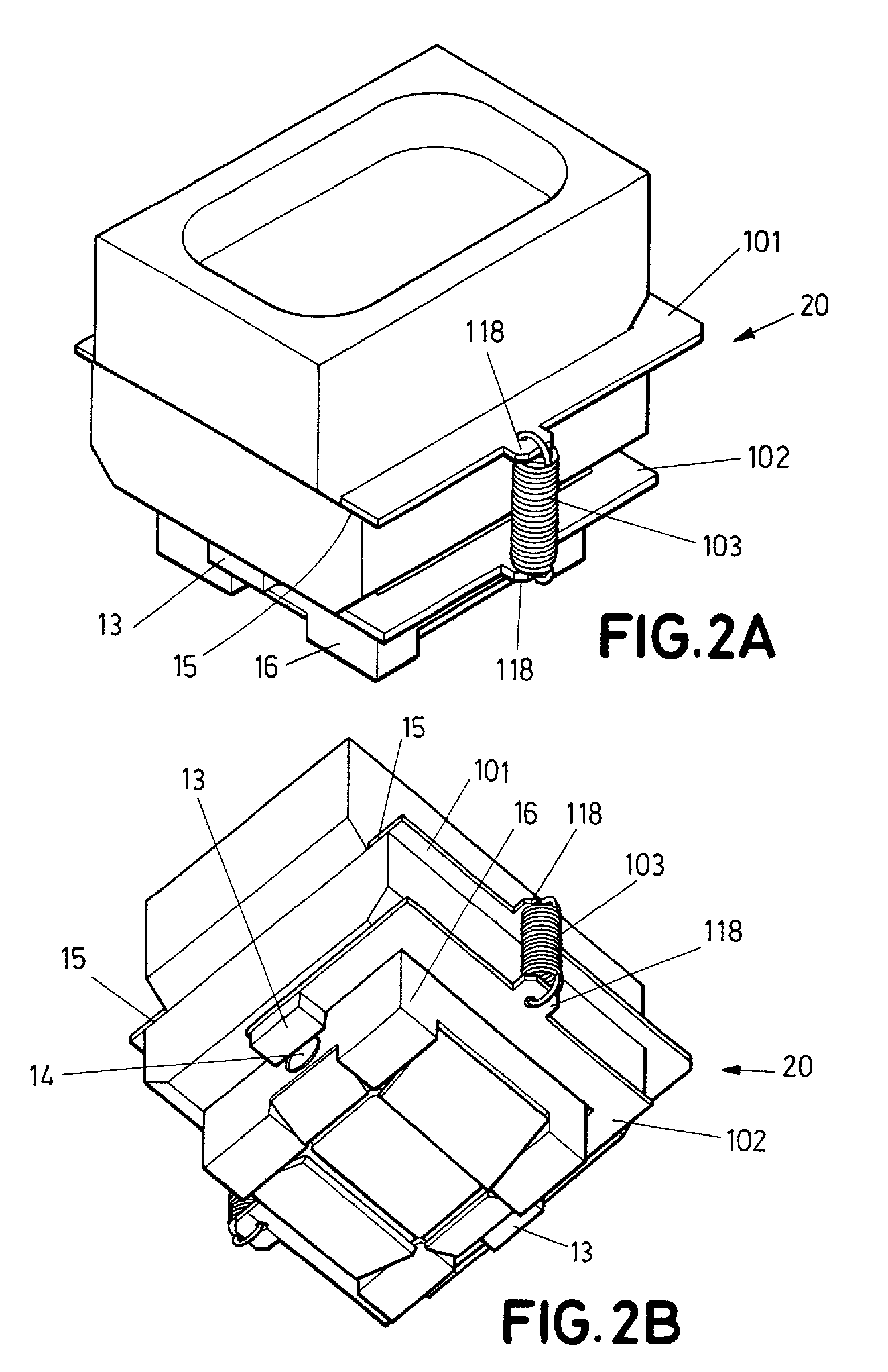
[0023]It is important that the strength of the magnets is sufficiently large to counteract the reaction force that is made by the mold-crucible set against the anchoring elements. Otherwise, this reaction force would be enough to separate the anchoring mechanism from the surface of the tube, rendering it inefficient.
[0024]The system object of the present invention features a second difference with respect to patent application P201030202 which has to do with the opening for the input of the cable into the mold-crucible. In that application, the mold-crucible is featured with an opening appropriately sized to introduce a cable with a certain section through it. To perform welding on a cable having a different section it is necessary to choose a different mold-crucible, i.e., with an appropriately sized opening for the new section of the cable. Presented in the current application are a series of bushings complementary to the opening of the mold-crucible, which may modify the latter's size, and thus enable the use of the same mold-crucible with cables of different sections.
[0026]The bushing incorporated in the mold-crucible has a conical inner surface. The conicity of this surface is equal to the conicity of the exterior surface of the complementary bushing corresponding to another section of the cable. For this reason, when the second bushing is introduced into the first, it will be enough to lightly push to obtain a conical adjustment between both surfaces, which will guarantee the connection between the two bushings due to the strong friction force that will appear. For this reason, the lack of clearance between both bushings will be guaranteed, ensuring that there will be no leaks of molten metal from the aluminothermic reaction.

Problems solved by technology

Furthermore, the lower the temperature that the tube reaches, the lower the risk of inflammation of the volatile components associated with the gas pipeline.

Method used


Image

  • Mold crucible system for connecting tubes and cables and method thereof
  • Mold crucible system for connecting tubes and cables and method thereof
  • Mold crucible system for connecting tubes and cables and method thereof

Examples


Embodiment Construction

[0011]The system and process of welding object of the invention, like the object of the invention in patent application P201030202, enables to make electric connections between conductive cables of different sections and the surface of steel tubes of different diameters, without the temperature of the tube's surface exceeding a predetermined value. Both have similarities with what was described in the aforementioned utility model, U8702866 since it takes advantage of the heat that is generated in the aluminothermic reaction and it eliminates the possibility of structural changes in the steel, given that they allow for the placement of a small plate between the cable and the area where the welding is to be made. This plate incorporates, on the side in contact with the steel surface, the alloy with a low fusion point. Like in the case above, the heat produced by the aluminothermic reaction will melt the low fusion point alloy so that it will be possible to weld, simultaneously, the af...


PUM

PropertyMeasurementUnit
lengthaaaaaaaaaa
magnetic fieldaaaaaaaaaa
diameteraaaaaaaaaa

Abstract

A new anchoring mechanism for the mold-crucible set to the tube, to which the cable is to be welded is described, and the inclusion and use of some bushings which are inserted between the cable and the mold.

Description

[0001]This application claims priority to Spanish Patent Application No. P201131538, filed Sep. 23, 2011.OBJECT OF THE INVENTION[0002]The present invention refers to a system and a process of connection though welding to make electric connections between conductive cables of different sections and the surface of steel tubes of different diameters.[0003]The object of the invention allows making electric connections between conductive cables of different sections and the surface of steel tubes of different diameters, without the temperature of the tube's surface exceeding a predetermined value.BACKGROUND OF THE INVENTION[0004]When it is desirable to implement cathodic protection in tubes conducting gas in their interior, it is necessary to weld a cable with a certain section to the exterior surface of the tube. This cable will itself be connected to a sacrificial anode.[0005]The welding process to make electric connections between the conductive cables and the surface of the tubes mus...

Claims


Application Information

Patent Timeline
Patent Type & Authority Patents(United States)
IPC IPC(8): B23K37/00B23K31/02C21B15/00B22D41/00
CPCB23K23/00B23K37/0264B23K1/0006
Inventor DUART LVAREZ DE CIENFUEGOS, DANIEL
Owner KLK ELECTRO MATERIALES S L U
Why Eureka
Try Eureka