Mandrel tool probe for friction stir welding having physically-separate spiraled surfaces

a tool probe and spiral surface technology, applied in the direction of manufacturing tools, soldering devices, auxillary welding devices, etc., can solve the problems of small fragments of the probe in the joint material, prone to breakage, and less effective probes, so as to improve the material flow, improve the mixing effect, and the stir zone size

Inactive Publication Date: 2013-11-12
BURFORD DWIGHT A +1
View PDF21 Cites 18 Cited by
  • Summary
  • Abstract
  • Description
  • Claims
  • Application Information

AI Technical Summary

Benefits of technology

[0009]Example embodiments of the present disclosure are generally directed to a mandrel tool probe that includes spiraled surfaces instead of threads, grooves, channels or the like, and which may promote better material flow around the tool probe in FSW processes. The mandrel tool probe of example embodiments may promote better mixing and produce an increase in the size of the thermal mechanical zone (TMAZ) adjacent to the stir zone (nugget) when compared to the TMAZ produced by a similar-sized conventional threaded tool probe. An increase in the size of the stir zone may also be expected to enhance other similar welding processes such as friction stir processing (FSP), friction stir spot welding (FSSP) or the like.

Problems solved by technology

However, threads tend to break (“shed”) with use during the FSW process, leaving small fragments of the probe in the joint material and rendering the probe less effective.
Even when a chamfer is machined into the end of the probe, the threads become partial threads at this location and are prone to breakage (especially during the plunging phase of a typical FSW cycle).

Method used


Image

  • Mandrel tool probe for friction stir welding having physically-separate spiraled surfaces
  • Mandrel tool probe for friction stir welding having physically-separate spiraled surfaces
  • Mandrel tool probe for friction stir welding having physically-separate spiraled surfaces

Examples


Embodiment Construction

[0033]Some example embodiments of the present disclosure will now be described more fully hereinafter with reference to the accompanying drawings, in which some, but not all embodiments of the disclosure are shown. Indeed, various example embodiments of the disclosure may be embodied in many different forms and should not be construed as limited to the example embodiments set forth herein; rather, these example embodiments are provided so that this disclosure will be thorough and complete, and will fully convey the scope of the disclosure to those skilled in the art. Like reference numerals refer to like elements throughout.

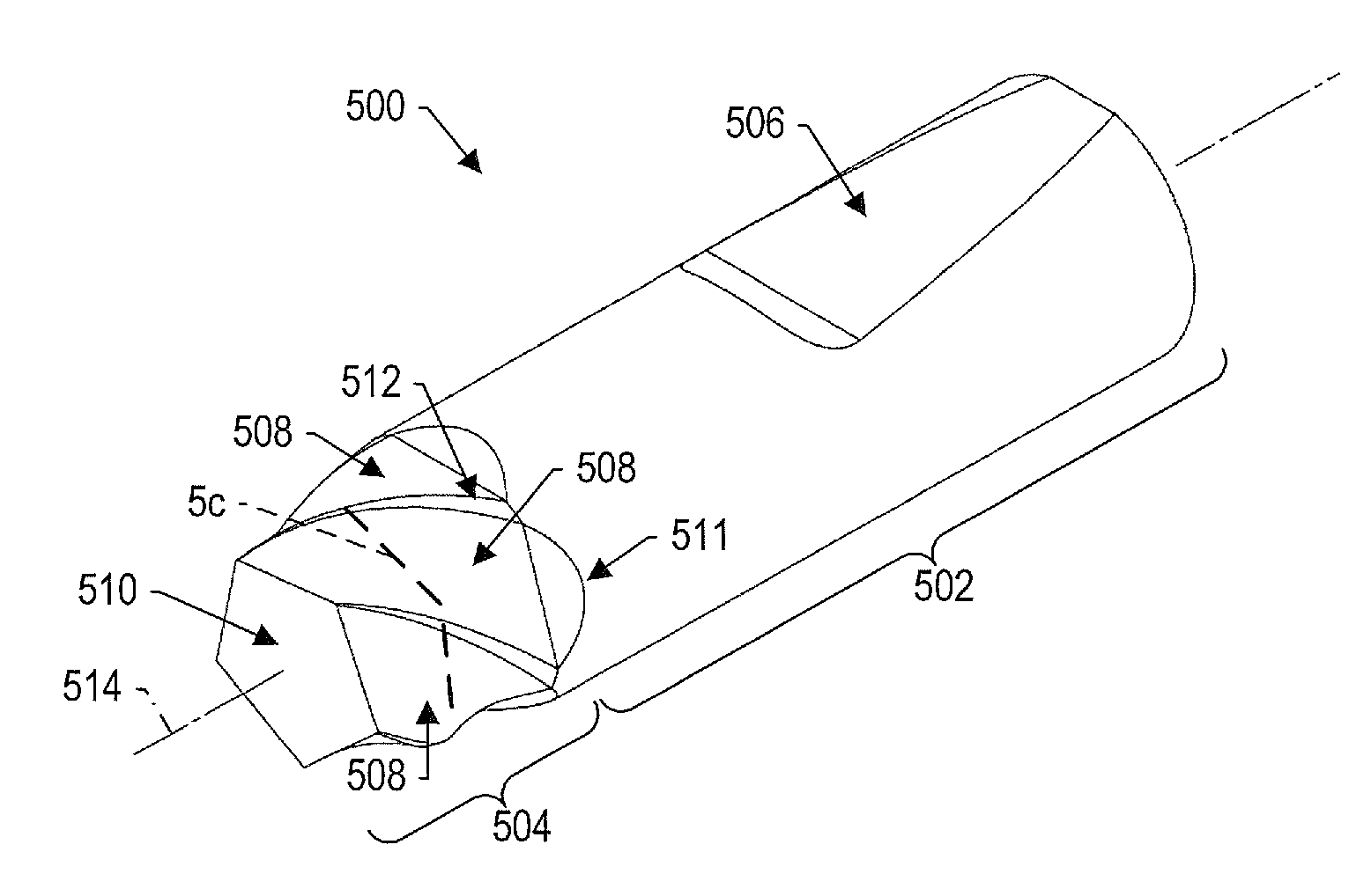
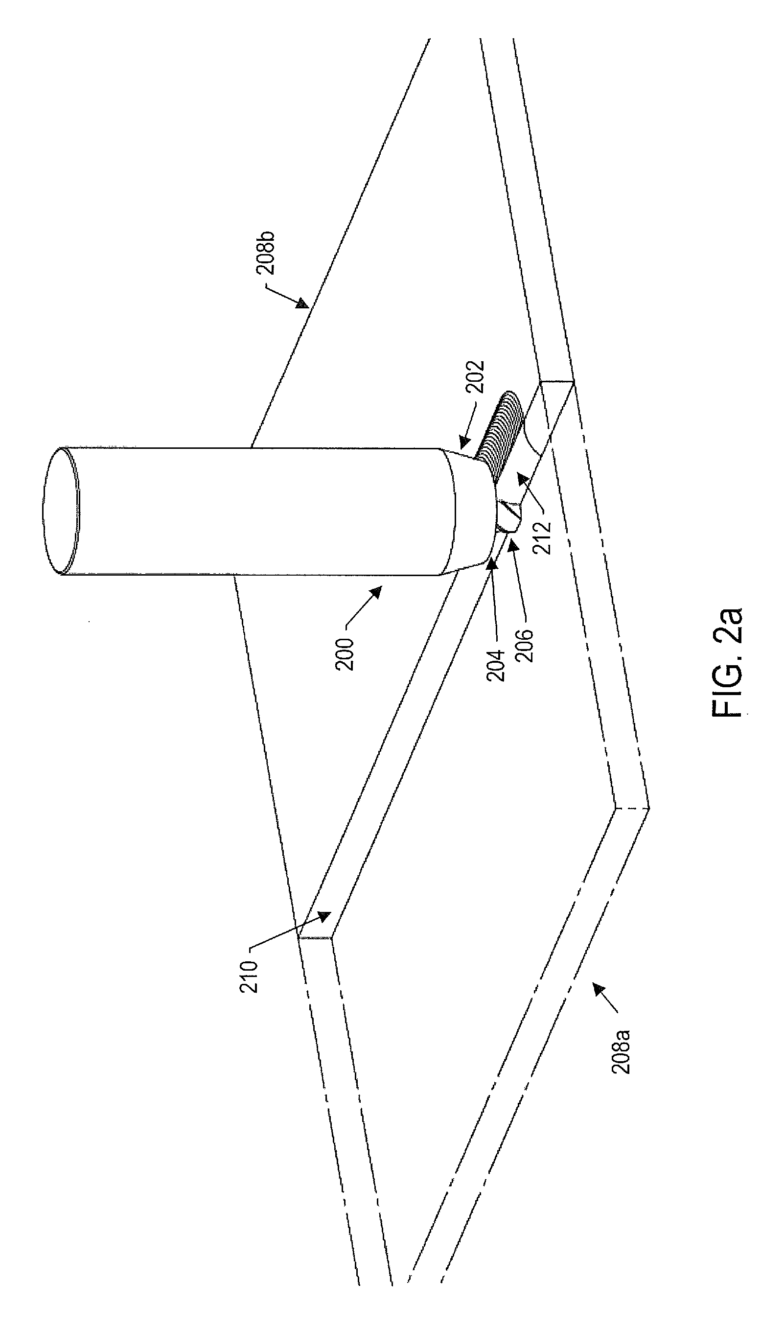
[0034]Example embodiments of the present disclosure are directed to a friction stir welding (FSW) weld tool probe referred to herein as a mandrel tool probe. FIG. 2 (including FIGS. 2a and 2b) illustrates a basic FSW tool and FSW process that may benefit from the mandrel tool probe of example embodiments. FIG. 2 illustrates the process used to fabricate a butt jo...


PUM

PropertyMeasurementUnit
spiral angleaaaaaaaaaa

Abstract

A mandrel tool probe is provided for performing a friction-stir process. The mandrel tool probe includes a shank and a tip coupled to the shank, where the shank and tip are concentric and rotatable about a given axis. The tip includes a set of a plurality of physically-separate, spiraled surfaces each of which has a linear or curved cross-section that extends along a length of the tip at a constant or varying spiral angle around the circumference of the tip. The tip also has a cross-section with a constant shape along the length of the tip, with the cross-section of the tip including a plurality of major segments each of which is formed of the cross-section of a respective spiraled surface.

Description

CROSS-REFERENCE TO RELATED APPLICATION(S)[0001]The present application is related to U.S. Provisional Patent Application No. 61 / 538,424, entitled: Tool Probe for Friction Stir Welding, filed on Sep. 23, 2011, the content of which is incorporated herein by reference in its entirety.TECHNOLOGICAL FIELD[0002]The present disclosure relates generally to non-consumable tools for friction stir welding and, more particularly, relates to tool probes and methods for forming joints between workpiece components by friction stir welding.BACKGROUND[0003]Friction stir welding is a solid-state (sub-solidus) joining process typically applied to metallic materials. It involves forcing a spinning, non-consumable tool into and along a joint between two or more workpieces to be permanently joined. A fully consolidated metallurgical joint may be formed between the workpieces as a result of the mechanical stirring and frictional heat introduced into the joint by the rotating, moving (traversing) tool. A c...

Claims


Application Information

Patent Timeline
Patent Type & Authority Patents(United States)
IPC IPC(8): B23K20/12B23K31/02
CPCB23K20/1255
Inventor BURFORD, DWIGHT A.
Owner BURFORD DWIGHT A
Why Eureka
Try Eureka