Device for separating fuel components

a technology for separating devices and fuel components, applied in special data processing applications, gaseous engine fuels, water/sewage treatment, etc., can solve problems such as difficulty in separating devices for fuel components, and achieve the effect of cooling down the remaining low-octane fuel

Inactive Publication Date: 2013-11-12
TOYOTA JIDOSHA KK +1
View PDF54 Cites 35 Cited by
  • Summary
  • Abstract
  • Description
  • Claims
  • Application Information

AI Technical Summary

Benefits of technology

[0007]Therefore, an object of the present invention is to provide a device for separating fuel components, which can sufficiently cool down the low-octane fuel remaining when high-octane fuel components are separated by means of the separating membrane without a large heat exchanger.
[0013]According to the third device for separating fuel components of the present invention, in the second device, in a low vehicle speed condition when a speed of the vehicle on which the third device is mounted is lower than a predetermined speed, the un-separated fuel at the set flow rate larger than the set flow rate in the engine idle condition is supplied to the separating membrane to separate high-octane fuel components, and the air cooling apparatus has the cooling ability which can change a gas phase part of the low-octane fuel remaining when the high-octane fuel components are separated from the un-separated fuel at both set flow rates in the low vehicle speed condition and the engine idle condition to an almost liquid phase. Thus, in both the low vehicle speed condition and the engine idle condition, with the air cooling apparatus, the low-octane fuel can be made to pass through the heat exchanger as the second liquid.

Problems solved by technology

Therefore, to sufficiently cool down the low-octane fuel including the gas phase, a very large heat exchanger is required, and it is thus difficult for the device for separating fuel components with such a very large heat exchanger to be mounted on a vehicle.

Method used


Image

  • Device for separating fuel components
  • Device for separating fuel components

Examples


Embodiment Construction

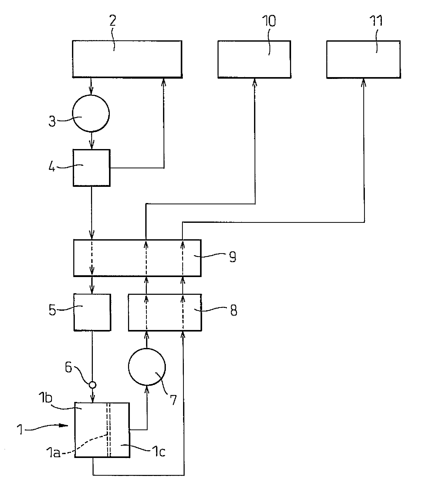
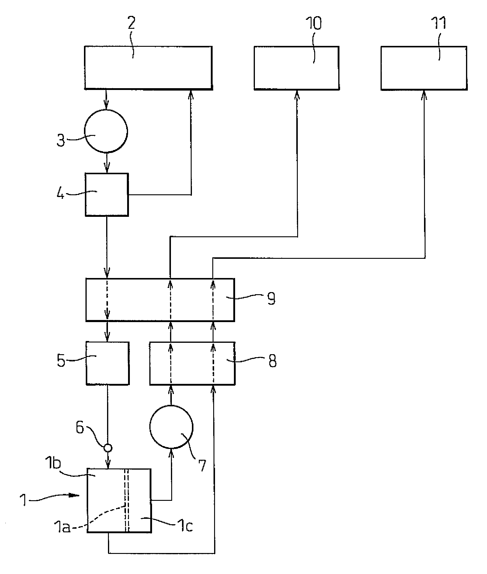
[0015]FIG. 1 is a schematic vertical sectional view showing a device for separating fuel components according to the present invention. In FIG. 1, reference numeral 1 designates a station for separating fuel components comprising a first section 1b and a second section 1c which are divided by a separating membrane 1a permeating aromatic components. Un-separated fuel pressurized at a relative high pressure by a fuel pump 3 is supplied to the first section 1b from an un-separated fuel tank 2 for storing the un-separated fuel. Reference numeral 4 designates a regulator for regulating a flow rate of the un-separated fuel supplied to the first section 1b. Reference numeral 5 designates a heater for heating the pressurized un-separated fuel immediately before supplying to the first section1b. The heater 5 utilizes, for example, the heat of the exhaust gas. However, the heater 5 may be an electric heater. Reference numeral 6 is a temperature sensor for measuring a fuel temperature heated b...


PUM

PropertyMeasurementUnit
speedaaaaaaaaaa
flow rateaaaaaaaaaa
flow ratesaaaaaaaaaa

Abstract

A device for separating fuel components comprising a separating membrane for separating high-octane fuel components from un-separated fuel and a heat exchanger between first liquid passing through the heat exchanger and second liquid passing through the heat exchanger, is provided. The first liquid is un-separated fuel passing through the heat exchanger before being supplied to the separating membrane. The second liquid is low-octane fuel remaining when the high-octane fuel components are separated from the un-separated fuel, passing through the heat exchanger after changing to an almost liquid phase.

Description

BACKGROUND OF THE INVENTION[0001]1. Field of the Invention[0002]The present invention relates to a device for separating fuel components.[0003]2. Description of the Related Art[0004]For example, in an engine having a high compression ratio, high-octane fuel is needed to restrain knocking. However, in low engine load operations in which knocking rarely occurs, the engine may not be required to use high-octane fuel, but low-octane fuel. Accordingly, it is suggested that the engine not use high-octane fuel (high-octane gasoline) which is expensive, but regular gasoline which is separated into high-octane fuel components and the remaining fuel as low-octane fuel by a device for separating fuel components.[0005]The device for separating fuel components separates aromatic components as high-octane fuel components from fuel by means of a separating membrane and makes the remaining fuel low-octane fuel. In such a device for separating fuel components, un-separated fuel is preferably heated ...

Claims


Application Information

Patent Timeline
Patent Type & Authority Patents(United States)
IPC IPC(8): B01D61/36C10G31/09
CPCB01D61/36C10G31/09B01D2313/38C10G2300/305Y10T137/86187B01D2313/221
Inventor PARTRIDGE, RANDALL D.WALCHUK, GEORGESUGIYAMA, KOUSEKI
Owner TOYOTA JIDOSHA KK
Why Eureka
Try Eureka