Fibre matrix and a method of making a fibre matrix

a technology of fibre matrix and fibre matrix, which is applied in the field of fibre matrix, can solve the problems of significant carbon fibre breakage within the body of the preform, prohibit the use of the preform in high wear applications, and non-woven materials subjected to intensive heat treatment and often shrinkag

Active Publication Date: 2013-11-12
CARBON FIBER PREFORMS
View PDF74 Cites 13 Cited by
  • Summary
  • Abstract
  • Description
  • Claims
  • Application Information

AI Technical Summary

Benefits of technology

[0082]It is desirable that flow of the liquid carrier from the starting material through the substrate is relatively quick. In one embodiment, the velocity of the liquid carrier is 1 m / s or more, such as 2 m / s or more, 3 m / s or more, 4 m / s or more or 5 m / s or more. In another embodiment, the velocity of the liquid carrier is 10 m / s or more.
[0229]One or more sheets of matrix may be combined with a layer of aramid fibres. Preferably two or more layers of matrix may be combined with one or more layers of aramid fibres. In one embodiment the one or more sheets of matrix have a thickness of lmm. The thickness may be from 0.5 mm to 100 mm. Preferably the thickness may be from 0.75 mm to 75 mm. The thickness may be from lmm to 50 mm. It has been found that the binder in the matrix acts as an adhesive for the aramid fibres. It has been found that resulting mate advantageous properties in being lightweight and having a high impact resistance.

Problems solved by technology

Non-woven materials have to be subjected to intensive heat treatments and often shrink during the carbonisation process.
Furthermore it is well known in the art that carbon fibre has a friable nature and that overuse of compression forces will result in significant breakage of carbon fibre within a body of the preform.
If the fibre volume fraction is insufficiently high prior to densification, the material may be suitable for less demanding ablative applications but low fibre volume fractions can prohibit the use of the preform in high wear applications such as performance brake applications.
Consequently it may take a considerable period of time, such as several weeks, to produce the preform.

Method used


Image

  • Fibre matrix and a method of making a fibre matrix
  • Fibre matrix and a method of making a fibre matrix
  • Fibre matrix and a method of making a fibre matrix

Examples


example 1

[0255]A 0.0968 m2 sample was prepared using the process of the invention.

[0256]A starting material was prepared using:[0257]480 g of a fibre blend (50 wt % 25 mm carbon fibre and 50 wt % 50 mm carbon fibre)[0258]12 kg of water[0259]120 g of binder (acrylic based binder system)

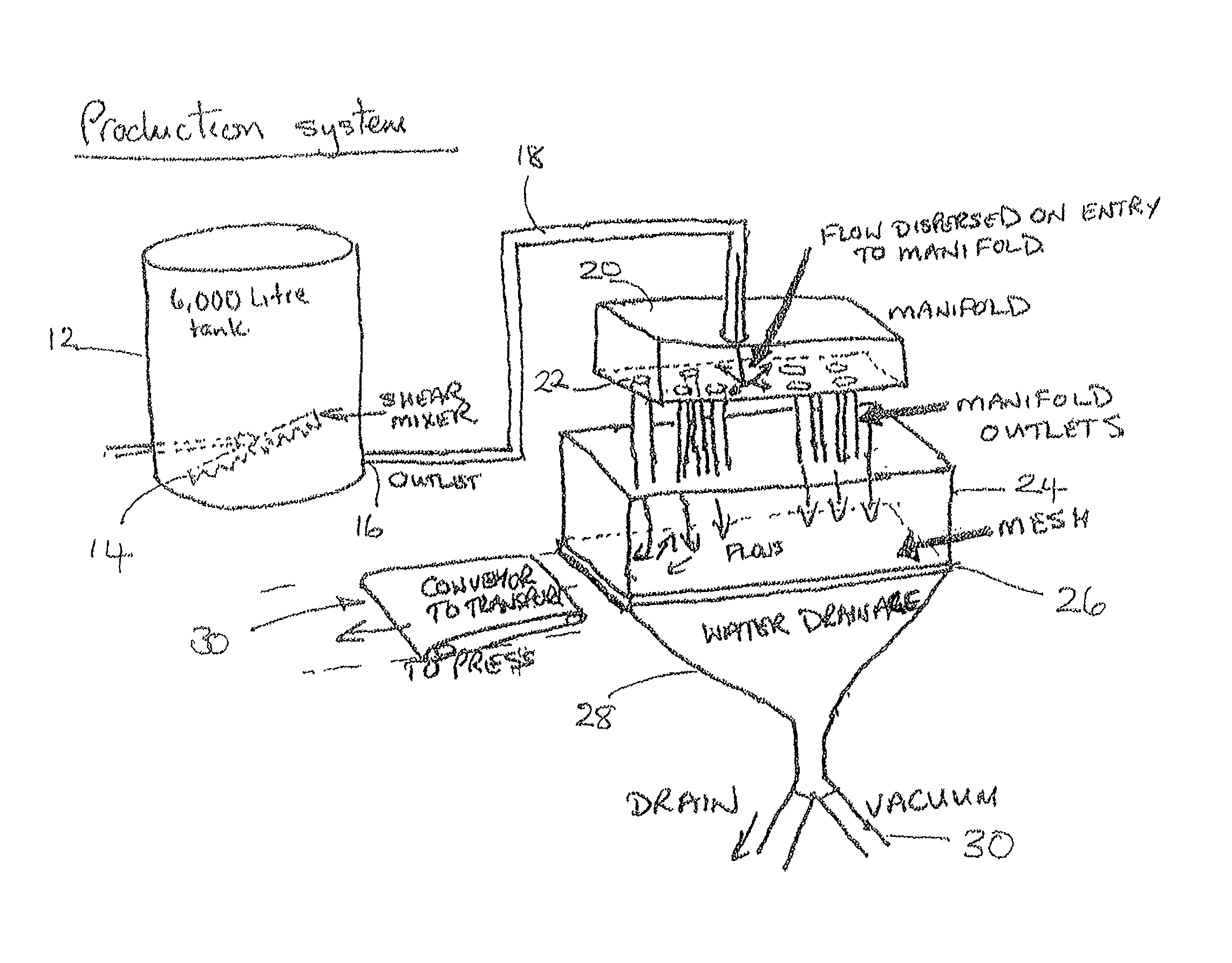
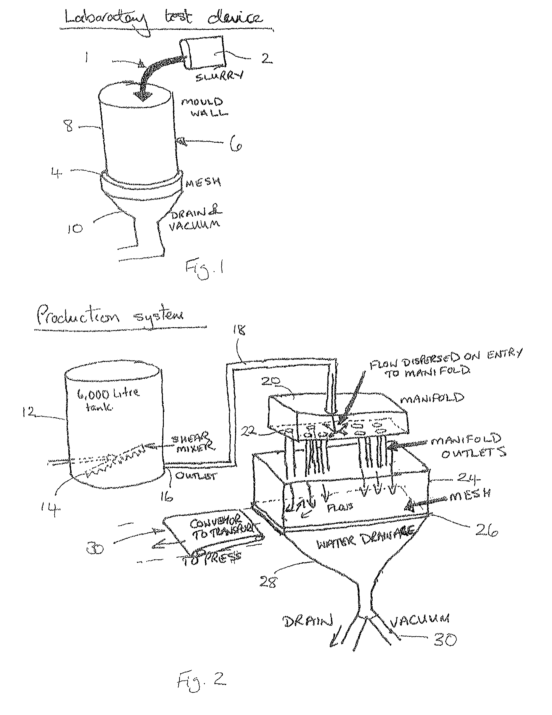
[0260]This starting material was dropped over a mesh substrate so as to deposit fibres onto the substrate, and then subjected to a vacuum force of approximately 550 torr before then being heated to a temperature of 170° C. under a compression force of 70 N / cm2.

[0261]A sheet of 10.2 mm thick, with a fibre volume of 23% and basis weight of 4000 gm2, was produced. A void content of approximately 69% was present in the product of this example.

example 2

[0262]A further sample was prepared using the same methods and materials as in Example 1. However, 30 wt % of colloidal silica was added to the starting material.

[0263]The final fibre volume fraction in this case was 26%, with a thickness of 8.2 mm and basis weight of 3650 gm2. A void content of approximately 60% was present in the product of this example.

examples 3-8

[0264]In all these examples, a 10 kg, 20 kg or 30 kg batch of the end product was made.


PUM

PropertyMeasurementUnit
pressureaaaaaaaaaa
Reynolds numberaaaaaaaaaa
volume fractionaaaaaaaaaa

Abstract

A method of forming a three dimensional fiber structure is disclosed which comprises the steps of a) providing a starting material which comprises liquid carrier, fibers and binder; b) passing the starting material over a substrate so as to deposit fibers onto the substrate; c) forming a three dimensional fiber matrix; and d) curing the binder. The flow of material onto the substrate may be controlled such that the flow of a starting material over the substrate is chaotic and fibers are laid down in a three dimensional structure containing a high proportion of voids. The preform may be pressurized while moist and is cured under pressure. The fibers may comprise carbon fibers; recycled carbon fiber has been found to be particularly useful. The resulting preform may be stochastic and is suitable for use in ablative and braking applications.

Description

CROSS-REFERENCE TO RELATED APPLICATIONS[0001]This application is a National Stage entry of International Application No. PCT / GB2010 / 051171, filed Jul. 19, 2010, which claims priority to Great Britain Application No. 0912455.3, filed Jul. 17, 2009 and Great Britain Application No. 1010901.5, filed Jun. 29, 2010. The disclosures of the prior applications are incorporated in their entirety by reference.[0002]This invention relates a fibre based preform and to a method of making a fibre matrix for such a preform. The preform is suitable for use in ablative, high performance, friction, wear and corrosion resistant applications. In particular, the invention relates to a method of producing a carbon based matrix for use in high temperature applications such as brakes, rocket motor housings and the like.[0003]It is well known to manufacture preforms for use in carbon-carbon composite applications. Morgan in “Carbon Fibres and their Composites” details preforms and methods of producing such ...

Claims


Application Information

Patent Timeline
Patent Type & Authority Patents(United States)
IPC IPC(8): B28B1/26
CPCC04B35/62204C04B35/62685C04B35/6269C04B35/6316C04B35/63416C04B35/63424C04B35/63436C04B35/63444C04B35/63452C04B35/63456C04B35/6346C04B35/63488C04B35/803C04B35/83D21H13/50F16D69/026F41H5/0471F41H5/0485B29B11/16B01J6/008B29C41/02D04H1/64F16D69/023C04B35/6263Y10T428/1362C04B2235/3418C04B2235/422C04B2235/5248C04B2235/5264C04B2235/5268C04B2235/5272C04B2235/5436C04B2235/604C04B2235/608C04B2235/614C04B2235/95Y10T442/60Y10T428/24994B33Y10/00C04B35/80C04B35/14B33Y70/10D21F9/00B32B18/00B29C70/30
Inventor BELL, DAVIDPRICE, ROY G.
Owner CARBON FIBER PREFORMS
Why Eureka
Try Eureka