High-side driver circuit

a driver circuit and driver circuit technology, applied in the direction of oscillator generators, electronic switching, pulse techniques, etc., can solve the problems of increasing on-resistance, reducing and inability to control, so as to reduce the performance of depletion-mode transistors

Active Publication Date: 2013-11-12
NAT CHIAO TUNG UNIV
View PDF13 Cites 18 Cited by
  • Summary
  • Abstract
  • Description
  • Claims
  • Application Information

AI Technical Summary

Benefits of technology

[0017]A high side gate driver with the depletion-mode transistor is provided to improve the problem of insufficient charging time for the bootstrap capacitor, in order to complete the switch of the depletion-mode transistor without reducing the performance of the depletion-mode transistor and the need of a floating voltage source or a negative voltage source.

Problems solved by technology

Thus, the source of the power transistor is a floating voltage, which is unable to be used to control the switch of the transistor directly via a constant gate voltage.
The design for the high-side power transistor with the conventional bootstrap circuit is only applicable for the enhancement-mode transistor and is not the depletion-mode transistor, because the charging is not enough for the bootstrap capacitor upon driving the depletion-mode transistor.
However, this design will reduce the performance of the depletion-mode transistor, such as increase the on-resistance of composite device.
However, this design requires a floating voltage source, which is more complicated.
However, this design is not applicable for the high-side driver circuit with the bootstrap circuit.

Method used


Image

  • High-side driver circuit
  • High-side driver circuit
  • High-side driver circuit

Examples


Embodiment Construction

[0022]In order to further understand the features and the technical contents of the present invention, please refer to the following detail description of invention and attached Figures. The attached Figures are only used for the reference and description, which are not used to limit the present invention.

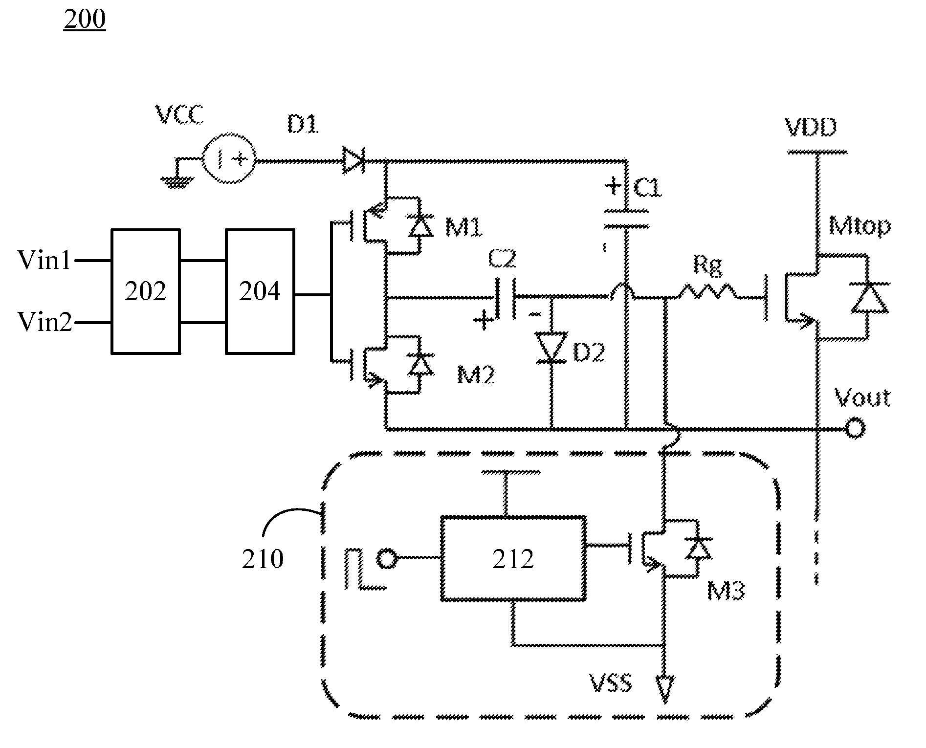
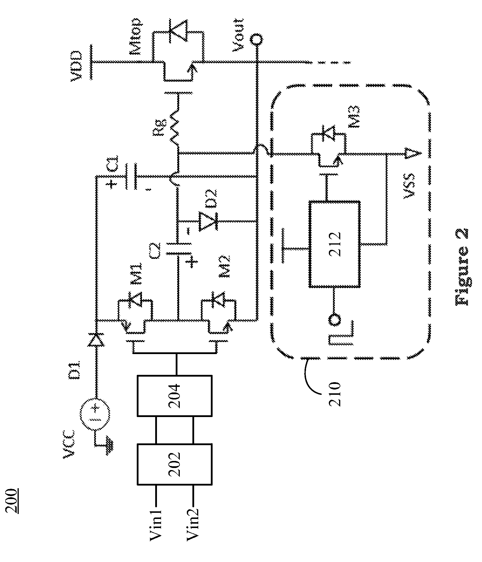
[0023]Please referring to FIG. 2, which is a diagram illustrating the high side gate driver with the depletion-mode transistor for an embodiment of the present invention. The difference between the depletion-mode transistor and the enhancement-mode transistor is that when its gate-source voltage VGS is negative, the transistor is turned off, and when its gate-source voltage VGS is zero, the transistor is conducted. Thus, it is necessary to design a circuit to control the turn on / off of the depletion-mode transistor. As shown in FIG. 2, a high-side driver circuit 200 is disclosed. The high-side driver circuit 200 includes a power transistor Mtop, the first transistor M1, the second ...


PUM


Abstract

The present invention provides a high-side driver circuit including a power transistor, the first transistor, the second transistor, the second capacitor, the second diode, a start-up circuit. The start-up circuit is coupled between a resistor and the second capacitor to complete a gate driving circuit. And, the aforementioned resistor can either be the gate resistance of the power transistor or an external resistor. The design of start-up circuit enables the functionality of the bootstrap capacitor of being charged to a designate voltage level. Thus, the depletion-mode transistor can be controlled to turn on / off without a floating voltage source or a negative voltage source.

Description

BACKGROUND OF THE INVENTION[0001]1. Field of the Invention[0002]The present invention, relates to a high-side driver circuit, more particularly to a high-side driver circuit combined with the bootstrap circuit and the depletion-mode transistor.[0003]2. Description of the Prior Art[0004]In the common high-efficiency and high-power system, the N-type device with better performance is used as the high-side power transistor. Thus, the source of the power transistor is a floating voltage, which is unable to be used to control the switch of the transistor directly via a constant gate voltage. The conventional method for solving the problem is that to adopt a bootstrap circuit to float the gate voltage with respect to the source voltage. The design for the high-side power transistor with the conventional bootstrap circuit is only applicable for the enhancement-mode transistor and is not the depletion-mode transistor, because the charging is not enough for the bootstrap capacitor upon drivi...

Claims


Application Information

Patent Timeline
Patent Type & Authority Patents(United States)
IPC IPC(8): H03B1/00
CPCH03K17/063H03K2217/0081H03K2217/0063
Inventor CHEN, TSUNG-LINCHANG, EDWARD YICHIENG, WEI-HUACHENG, STONEJENG, SHYR-LONGCHANG, CHE-WEI
Owner NAT CHIAO TUNG UNIV
Why Eureka
Try Eureka