Charge pump circuit

a pump circuit and discharge pump technology, applied in the field of control circuits, can solve the problem of limited and achieve the effect of reducing the locking time of the phase locked loop

Inactive Publication Date: 2013-11-12
IPGOAL MICROELECTRONICS (SICHUAN) CO LTD
View PDF7 Cites 7 Cited by
  • Summary
  • Abstract
  • Description
  • Claims
  • Application Information

AI Technical Summary

Benefits of technology

[0005]An object of the present invention is to provide a charge pump circuit which is capable of quickening the locking time of the phase locked loop.
[0015]Compared with the prior art, the charge pump circuit of the present invention can automatically adjust the charge and discharge currents based on the pulse width of the output signal of the phase frequency detector, thereby changing the loop bandwidth of the phase locked loop and quickening the locking time of the phase locked loop. Furthermore, when the phase locked loop is locked up, no extra power consumption is generated, namely, only a branch of working current is kept.

Problems solved by technology

In generally, the conventional charge pump circuit only has a branch of working current, so that the locking time of the phase locked loop is limited.

Method used


Image

  • Charge pump circuit
  • Charge pump circuit

Examples


Embodiment Construction

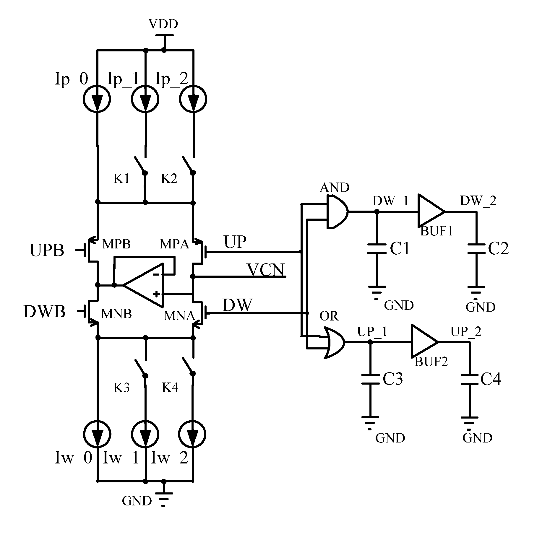
[0018]Referring to the drawing, a charge pump circuit according to a preferred embodiment of the present invention is illustrated, wherein the charge pump circuit comprises a control circuit and a switching circuit.

[0019]The control circuit comprises an AND gate AND, an OR gate OR, a first buffer BUF1 connected with the AND gate AND, and a second buffer BUF2 connected with the OR gate OR. Two input ends UP and DW of the control circuit are respectively connected with two input ends of the AND gate AND, and the two input ends UP and DW of the control circuit are respectively connected with two input ends of the OR gate OR. The output end of the AND gate AND is connected with ground through the capacitor C1. The AND gate AND outputs a signal DW_1 to the input end of the first buffer BUF1. The output end of the first buffer BUF1 outputs a signal DW_2 and is connected with ground through the capacitor C2. The output end of the OR gate OR is connected with ground through the capacitor C3...


PUM


Abstract

A charge pump circuit includes a switching circuit for providing a charge and discharge current, and a control circuit for controlling the switching circuit. The switching circuit includes a first switch for controlling the charging speed. The control circuit generates a signal for controlling the first switch based on the pulse width of the input signal. The charge pump circuit of the present invention quickens the locking time of the phase locked loop.

Description

BACKGROUND OF THE PRESENT INVENTION[0001]1. Field of Invention[0002]The present invention relates to a control circuit, and more particularly to a charge pump circuit which is capable of automatically adjusting the charge and discharge current based on the impulse width of the signal.[0003]2. Description of Related Arts[0004]The phase separation between the output signal and the input signal of the phase-locked loop (PLL) and delay-locked loop (DLL) is needed to be identified by the phase frequency detector. The phase separation is integrated by the charge pump such that the integral result is embodied in the control voltage in the form of the voltage variation. The control voltage is used to control the voltage control oscillator or voltage-controlled delay line till the phase synchronization between the two signals is achieved. In generally, the conventional charge pump circuit only has a branch of working current, so that the locking time of the phase locked loop is limited.SUMMA...

Claims


Application Information

Patent Timeline
Patent Type & Authority Patents(United States)
IPC IPC(8): H03L7/06
CPCH02M3/07
Inventor FAN, FANGPING
Owner IPGOAL MICROELECTRONICS (SICHUAN) CO LTD
Why Eureka
Try Eureka