
Digital phase-locked loop and digital-phase frequency detector thereof

A phase frequency, digital phase locking technology, applied in the direction of automatic power control, electrical components, etc., can solve problems such as complex structure, and achieve the effects of high resolution, large operating range and low power consumption

Inactive Publication Date: 2012-10-17
IND TECH RES INST
View PDF3 Cites 0 Cited by
  • Summary
  • Abstract
  • Description
  • Claims
  • Application Information

AI Technical Summary

Problems solved by technology

However, this structure is somewhat complicated, and it is necessary to change the different divisor settings of the frequency divider (that is, its internal frequency division multiplier) to maintain a fixed output frequency of the oscillator

Method used


Image

  • Digital phase-locked loop and digital-phase frequency detector thereof
  • Digital phase-locked loop and digital-phase frequency detector thereof
  • Digital phase-locked loop and digital-phase frequency detector thereof

Examples


Embodiment Construction

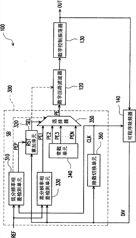
[0018] In order to design a digital phase frequency detector with low power consumption, high resolution, and large operating range, this embodiment proposes a new structure. figure 1 It is a block diagram illustrating a digital phase locked loop according to an embodiment of the present invention. Please refer to figure 1 , The digital phase locked loop 100 includes a digital phase frequency detector 300, a digital loop filter 120, a digitally controlled oscillator 130, and a programmable frequency divider 140. The input terminal of the programmable frequency divider 140 is coupled to the output terminal of the digitally controlled oscillator 130, and the phase-locked signal OUT output by the digitally controlled oscillator 130 is frequency-divided, and its output terminal provides a feedback signal DIV to Digital phase frequency detector 300. The digital phase frequency detector 300 receives the reference signal REF, detects the phase error between the reference signal REF an...


PUM


Abstract

The invention discloses a digital-phase frequency detector, which comprises a divisor switching unit, a low-resolution phase difference detection unit, an accumulating unit, a high-resolution phase difference detection unit, a constant unit and a selector, wherein the divisor switching unit is used for receiving and eliminating a part of pulses of a feedback signal so as to obtain a feedback clock; the low-resolution phase difference detection unit is used for detecting the phase difference between a reference signal and the feedback clock so as to obtain a phase-difference pulse width; the accumulating unit is used for accumulating the feedback signal within the phase-difference pulse width so as to obtain an output selection signal; the high-resolution phase difference detection unit isused for detecting the phase difference between the reference signal and the feedback signal so as to obtain a phase difference value; the a constant unit is used for providing at least a constant value; and the selector is used for selecting to output one between the phase difference value and the constant value according to the output selection signal.

Description

Technical field [0001] The present invention relates to a phase-locked loop (Phase-Locked Loop, PLL), and more particularly to a digital phase-locked loop (Digital PLL, DPLL) and a digital phase-frequency detector (Digital Phase-Frequency Detector, DPFD). Background technique [0002] The digitization of phase-locked loop (Phase-Locked Loop) is one of the important technologies in the development of wireless communication in recent years, because it is easier to implement in advanced system on chip (System on Chip), but it must be designed to be fast and low The noisy digital phase-locked loop (Digital Phase-Locked Loop) is a challenge. [0003] At present, digital phase-locked loops mainly face two problems. (1) Will the phase noise after digitization be lower than that of traditional analog phase-locked loops? (2) Can it support broadband phase modulation or fast phase lock? Therefore, a trade-off must be made between the loop bandwidth of the phase-locked loop and the phase n...

Claims


Application Information

Patent Timeline
Patent Type & Authority Patents(China)
IPC IPC(8): H03L7/085H03L7/08
Inventor 邱焕科阙资展
Owner IND TECH RES INST
Learn More