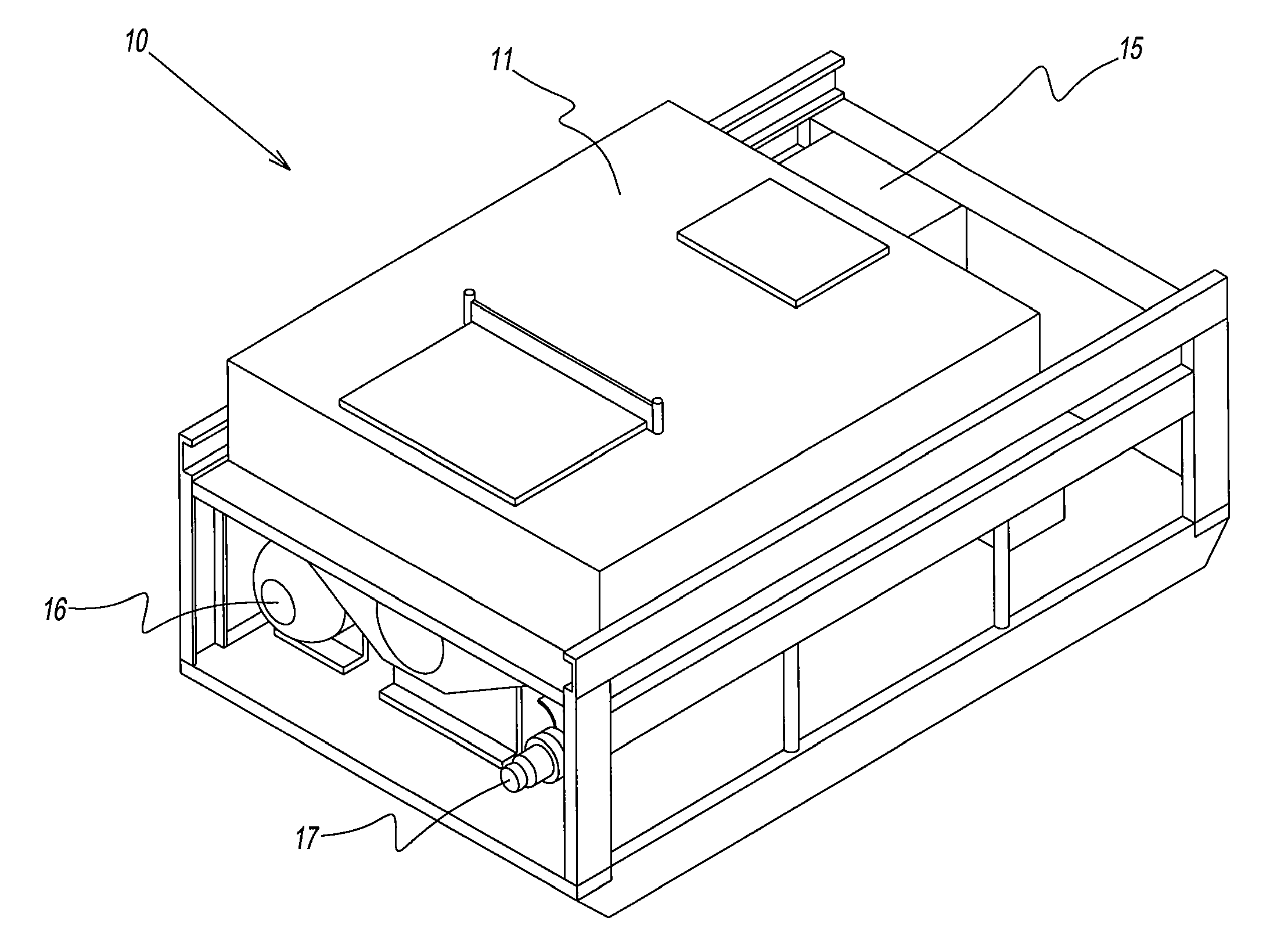
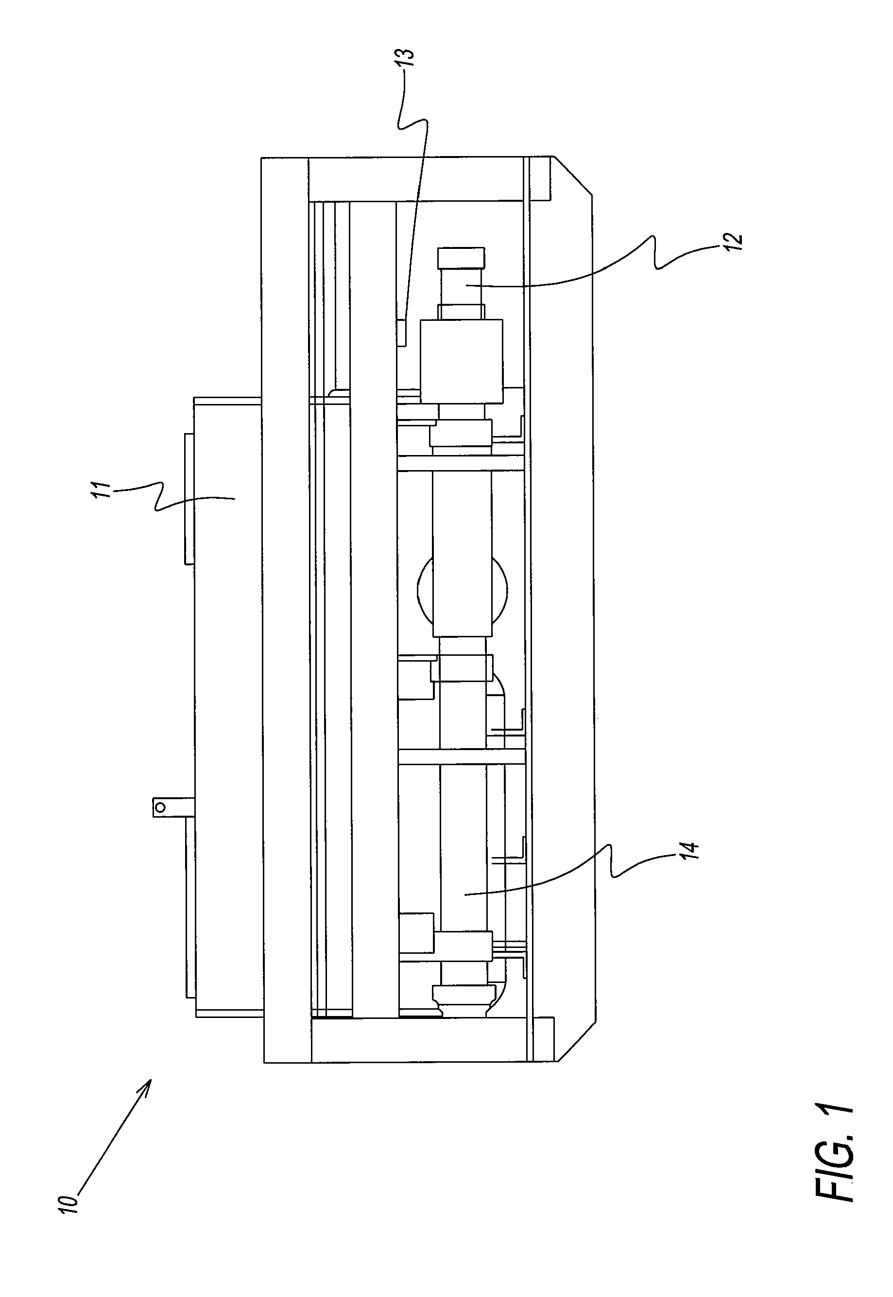
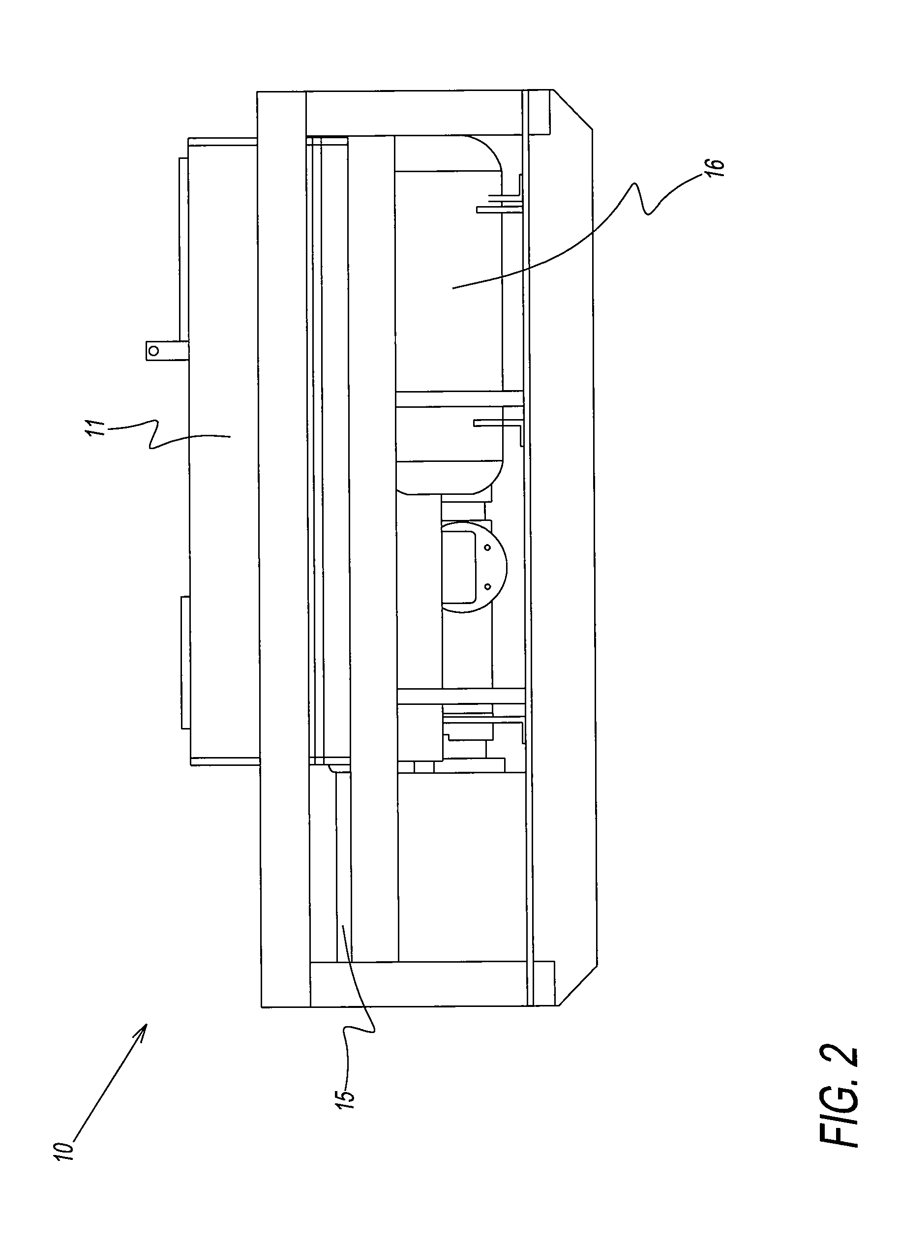
Rock dusting apparatus
a dusting apparatus and rock dust technology, applied in dust removal, applications, fire prevention, etc., can solve the problems of reducing the service life of the dusting apparatus, and reducing the risk of fire and explosion, so as to reduce the susceptibility to rock dust bridging, the effect of minimizing the wear of the parts which come and minimizing the susceptibility of the dust bridging
- Summary
- Abstract
- Description
- Claims
- Application Information
AI Technical Summary
Benefits of technology
Problems solved by technology
Method used
Image

Examples
examples
Operational Batching Procedures
[0153]The first step is to look into the mixing tank, e.g., 250 gallon batching tank, and check for it being clean. Then taking a clean out hose with a reducer for high pressure spray 150 psi or greater, clean the floor of the 250 gallon batching tank of any dry residue, and fill the tank to the desired gallons of water depending upon the mixture level utilized.
[0154]Next have the applicator in the scoop bucket with the hydraulic PTO connected. Have the PTO on, and pull the applicator lever for the air compressor to check to see that the air compressor that is on board the applicator is running and building pressure on the gauges near the valve bank. This assures that the PTO is properly hooked up. Then return the air compressor lever to the off position.
[0155]To the left of the three spool valve bank is located a diversion valve. With the PTO on, the next step is to lift the diversion valve to a position near the top of the applicator lid, opening ful...
PUM
 Abstract
Description
Claims
Application Information