Livestock cooling fan system

a fan array and livestock technology, applied in free-cooling systems, livestock management, liquid fuel engine components, etc., can solve the problems of difficult and/or expensive installation of systems, no known system which provides for large (i.e. greater than 45 degrees) or programmed simultaneous changes in the axial flow of fan arrays along a vertical plane, etc., to reduce installation costs, reduce installation time, and rapid installation

Active Publication Date: 2013-11-19
TERRELL MICHAEL
View PDF8 Cites 14 Cited by
  • Summary
  • Abstract
  • Description
  • Claims
  • Application Information

AI Technical Summary

Benefits of technology

The patent text describes a new cooling fan system that has several technical advantages over existing systems. First, it allows for vertical rotation of up to 90 degrees, which is unique compared to other systems. Second, the modular configuration of the truss structures allows for easy installation of identical fan modules, reducing installation time and cost. Third, the system allows for a linear array of fan modules to be rotated by a single rotation means, reducing complexity and maintenance. Finally, the system requires only one flexible electrical and water connection, making it more cost-effective and efficient. Overall, this patent describes an efficient and cost-effective cooling fan system that requires less on-site installation time and is suitable for livestock cooling.

Problems solved by technology

While such livestock systems may include some provision for adjustment of the vertical orientation of the axial flow, there is no known system which provides for large (i.e. greater than 45 degrees) or programmed simultaneous changes in the axial flow of a fan array along a vertical plane.
There are design difficulties which make such a system difficult and / or expensive to install which the inventor herein has overcome.
However, for rotation about a horizontal axis (referred to hereafter as vertical rotation), particularly a rotation which exceeds a change of axial flow direction of over ninety degrees, there are potential problems with achieving simultaneous rotation, as well as in providing the required delivery of electricity and water to each fan unit.

Method used


Image

  • Livestock cooling fan system
  • Livestock cooling fan system
  • Livestock cooling fan system

Examples


Embodiment Construction

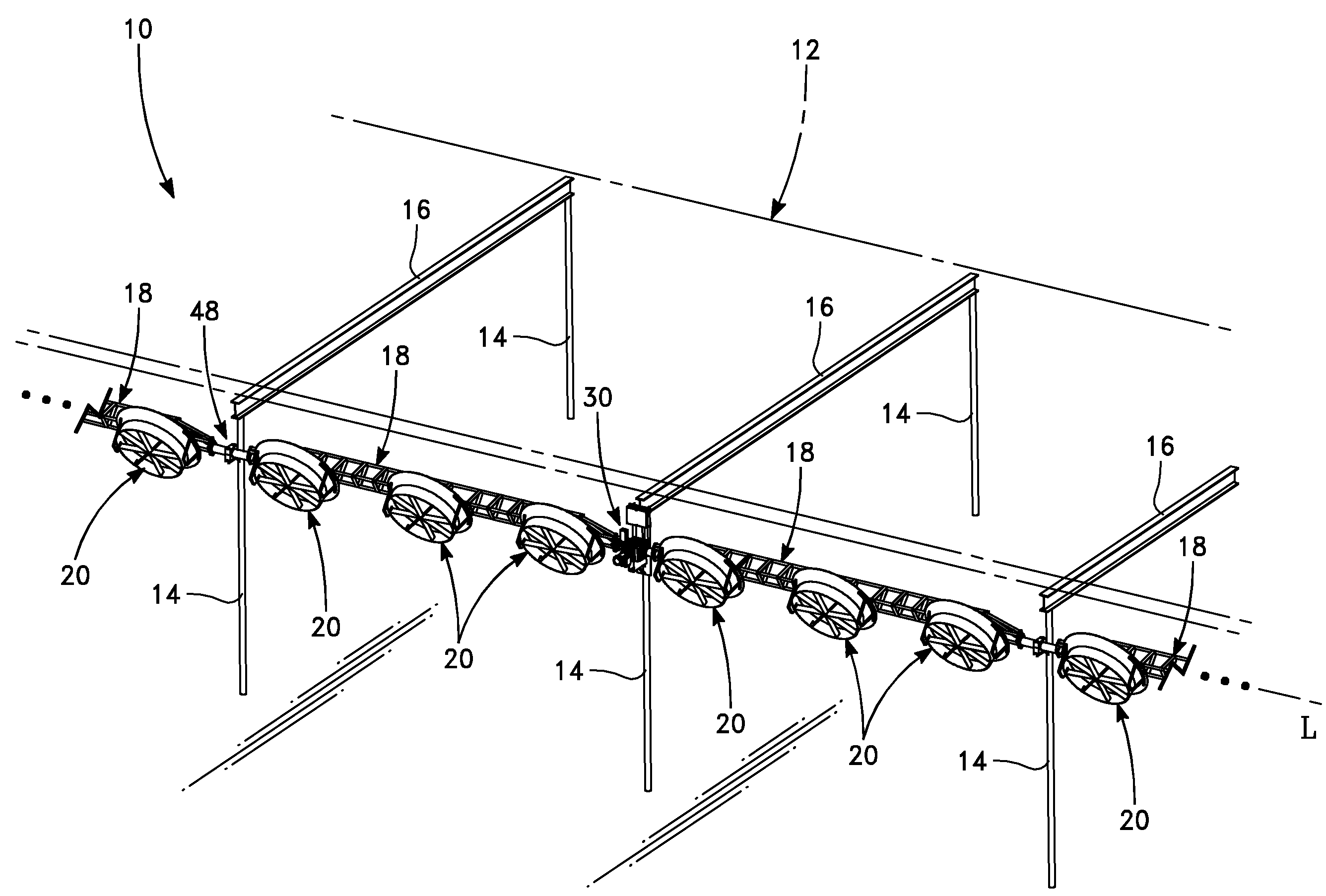
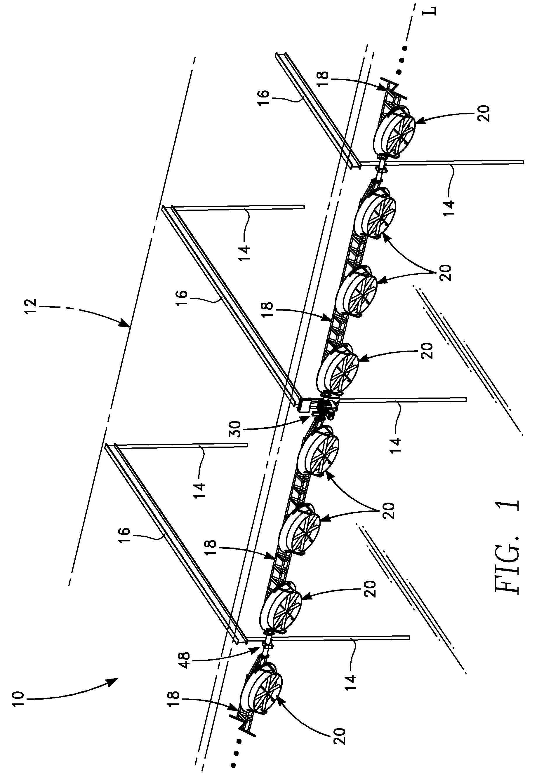
[0022]Referring now to the figures, a section of a cooling fan system 10 is depicted in FIG. 1. FIG. 1 generally depicts a livestock structure 12, which may be a simple shade structure, a milking barn, or other sheltering structure for livestock. Such a livestock structure 12 may comprise vertical columns 14, horizontal support beams 16 and a roof (not shown). For commercial dairies and livestock operations, the livestock structure 12 may be quite large, having sides extending hundreds of feet. Thus it is to be appreciated that FIG. 1 only depicts a section of a livestock structure 12 rather than the entire structure. As further suggested in FIG. 1, the cooling fan system 10 depicted in the figure is only a partial system. Generally, there may be a significant span between adjacent vertical columns 14, such as twenty to thirty feet. Thus the cooling fan system 10 must have sufficient structural integrity to span this distance, generally without external structural support except at ...


PUM


Abstract

A fan cooling system has individual fan modules which are connected together in an end-to-end configuration, where one of the fan modules is connected to a mechanism which rotates the linear array of fan modules. The fan modules are substantially identical, which allows prefabrication of the fan modules prior to on-site installation of the system. Each fan module may contain water injection piping and nozzles, which allows the fan cooling system to dispense fog. The linear array of fan modules may be rotated along a longitudinal axis, such that the axial flow direction of the fans may be changed with respect to a vertical plane. A suggested use of the fan cooling system is for the cooling of livestock in large livestock structures.

Description

CROSS-REFERENCE TO RELATED APPLICATIONS[0001]U.S. Provisional Application No. 61 / 301,498 for this invention was filed on Feb. 4, 2010, for which application this inventor claims domestic priority.BACKGROUND OF THE INVENTION[0002]The present invention generally relates to cooling systems of the type generally used for the cooling of livestock and more specifically to a programmable system for efficiently using cooling fans to create an environment which protects the health and productivity of animals.[0003]It is known in animal agriculture to cool livestock by the utilization of cooling fans. The known cooling systems typically use either fixed mounted fans, or fans which may be rotated about a vertical axis such that the angular orientation of the air flow from the fans may be varied along a horizontal plane, in either a fixed or oscillating manner. While the air flow from a fan may disperse in a variety of directions, particularly where diffusers are utilized, axial-flow fans have ...

Claims


Application Information

Patent Timeline
IPC IPC(8): F01D25/28
CPCA01K1/0082F24F6/14F24F5/0035A01K1/0052F04D29/58Y02B30/545Y02A40/76Y02A40/70Y02B30/54Y02P60/50Y02P60/12
Inventor TERRELL, MICHAEL
Owner TERRELL MICHAEL
Why Eureka
Try Eureka