
Chromatic point sensor compensation including workpiece material effects

a technology of chromatic point sensor and workpiece material, applied in the field of precision measurement instruments, can solve problems such as special calibration or compensation, and achieve the effects of reducing distance measurement errors, improving accuracy and robustness, and facilitating us

Active Publication Date: 2013-11-19
MITUTOYO CORP
View PDF9 Cites 13 Cited by
  • Summary
  • Abstract
  • Description
  • Claims
  • Application Information

AI Technical Summary

Benefits of technology

The patent describes a system that compensates for errors in a chromatic point sensor (CPS) by using distance-independent profile component compensation data. This compensation reduces errors caused by the reflectivity of the workpiece surface being measured relative to the material used for the distance calibration of the CPS. The system is easier to use and provides more accurate and robust error compensation compared to previous methods. The technical effect of this patent is to provide a better way to measure distances to workpieces, taking into account the reflectivity of the material being measured.

Problems solved by technology

It should be noted that the '242 patent does not disclose an embodiment that truly compensates for material spectral reflectivity variations at the level contemplated herein, because in the absence of special calibration or compensation, its embodiment remains susceptible to wavelength intensity weighting effects due to workpiece material reflectivity, and the '242 patent does not teach special calibration or compensation for adjusting a detected wavelength based on the reflecting material.

Method used


Image

  • Chromatic point sensor compensation including workpiece material effects
  • Chromatic point sensor compensation including workpiece material effects
  • Chromatic point sensor compensation including workpiece material effects

Examples


Embodiment Construction

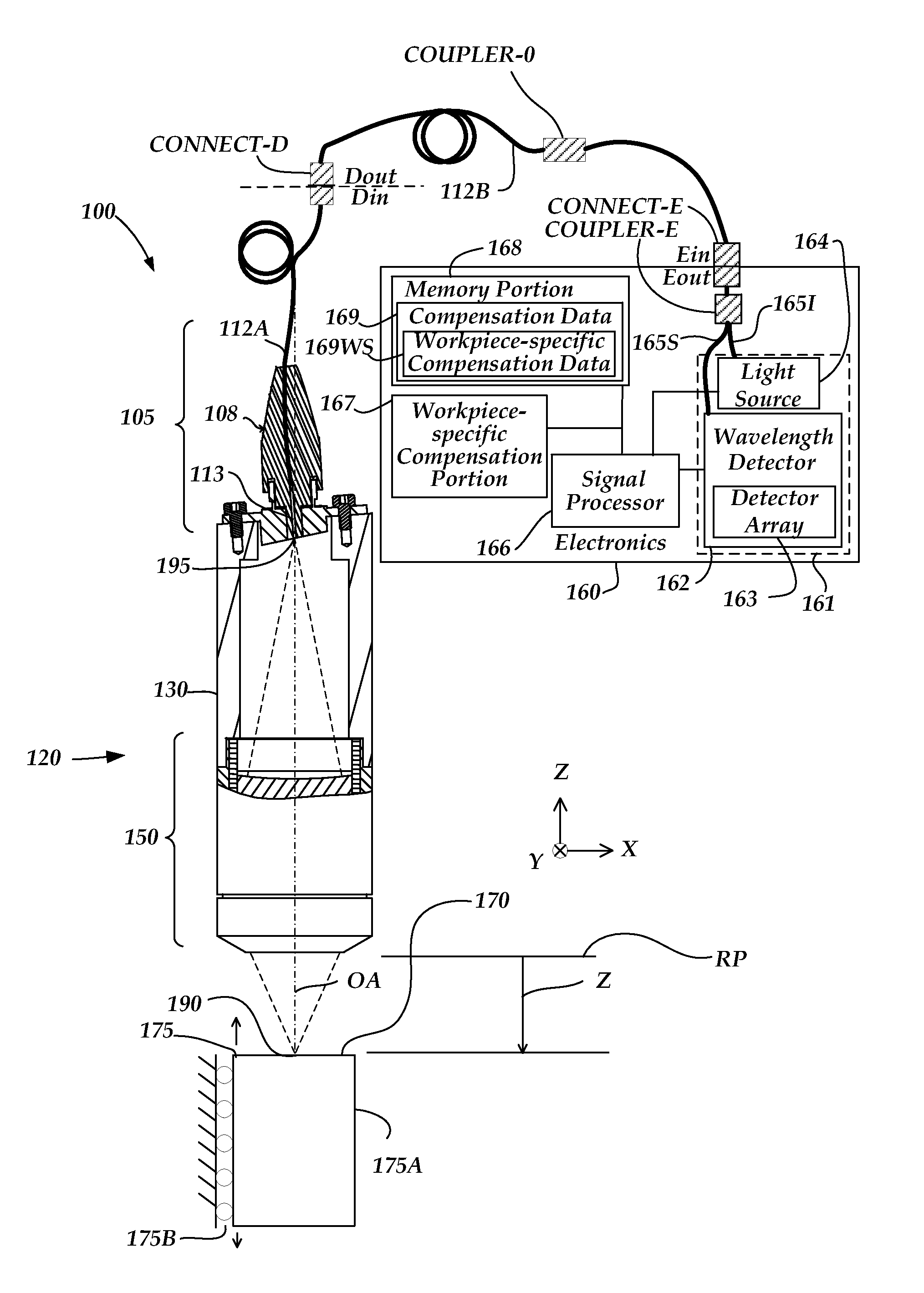
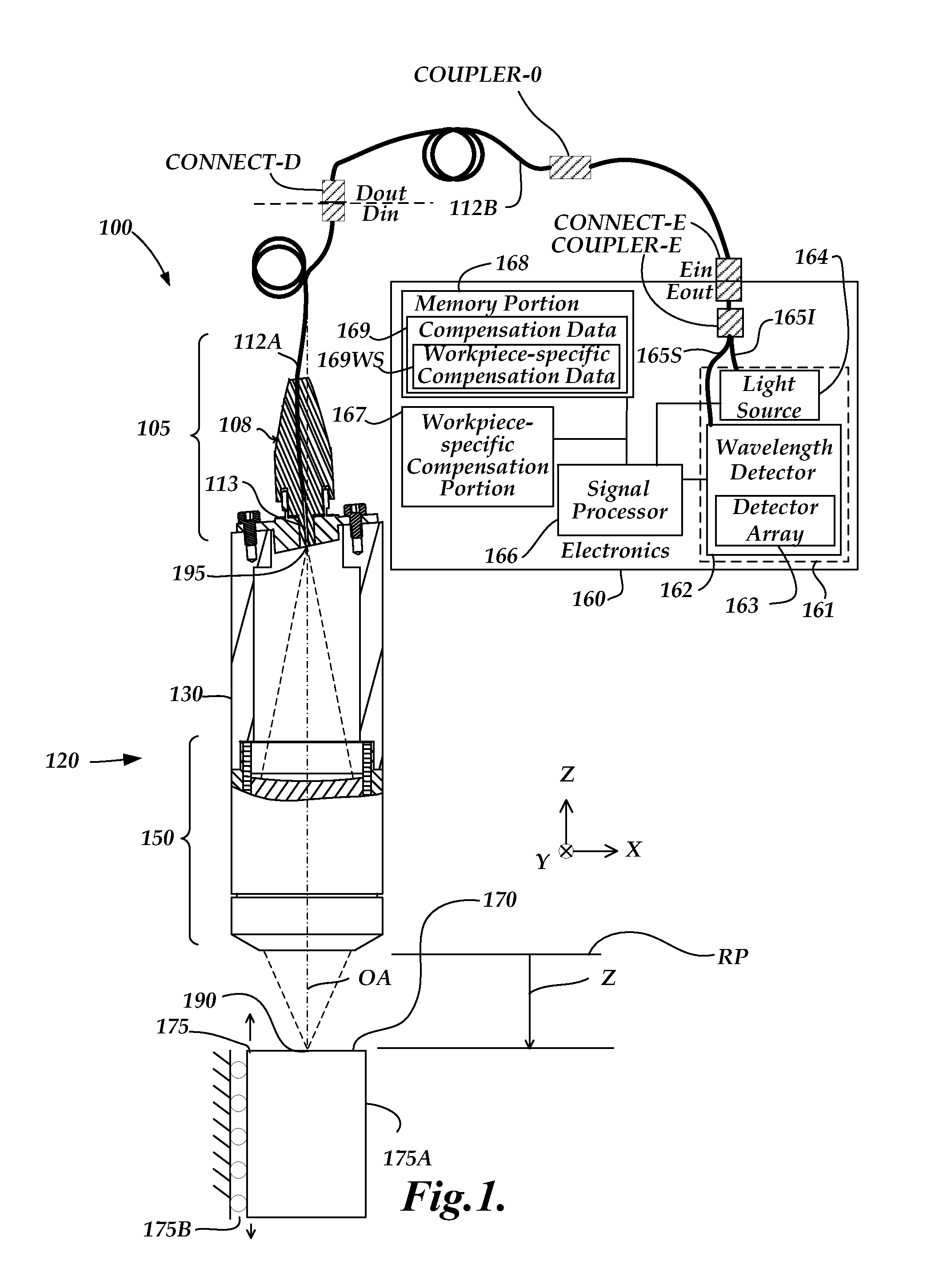
[0034]FIG. 1 is a block diagram of one exemplary embodiment of a chromatic point sensor (CPS) system 100. As shown in FIG. 1, the CPS system 100 includes an optical pen 120 and an electronics portion 160. In the embodiment shown in FIG. 1, the electronics portion 160 includes a signal processor 166, a memory portion 168 and a source+detector subsystem 161 comprising a wavelength detector 162, and a broadband light source 164 (also referred to as a white light source, in some embodiments). In various embodiments, the wavelength detector 162 includes a detector array 163 of a spectrometer. The detector array 163 may comprises a plurality of pixels distributed along a measurement axis of the wavelength detector 162, the plurality of pixels receiving respective wavelengths and providing output spectral profile data. The wavelength detector 162 may also include related signal processing (e.g., provided by the signal processor 166, in some embodiments) that removes or compensates certain ...


PUM


Abstract

A method of error compensation in a chromatic point sensor (CPS) reduces errors associated with varying workpiece spectral reflectivity. The errors are associated with a distance-independent profile component of the CPS measurement signals. Workpiece spectral reflectivity may be characterized using known spectral reflectivity for a workpiece material, or by measuring the workpiece spectral reflectivity using the CPS system. CPS spectral reflectivity measurement may comprise scanning the CPS optical pen to a plurality of distances relative to a workpiece surface and determining a distance-independent composite spectral profile from a plurality of resulting wavelength peaks. By comparing the distance-independent composite spectral profile obtained from a workpiece with that corresponding to the CPS distance calibration procedure, the contribution of the reflectivity characteristics of the workpiece will be indicated in the differences between the profiles, and potential CPS position errors due to varying workpiece reflectivity characteristics may be calculated and / or compensated.

Description

FIELD OF THE INVENTION[0001]The invention relates generally to precision measurement instruments, and more particularly to chromatic point sensors and similar optical distance determining devices and their use.BACKGROUND OF THE INVENTION[0002]It is known to use chromatic confocal techniques in optical height or distance sensors. As described in U.S. Pat. No. 7,876,456 (the '456 patent), which is hereby incorporated herein by reference in its entirety, an optical element having axial chromatic aberration, also referred to as axial or longitudinal chromatic dispersion, may be used to focus a broadband light source such that the axial distance to the focus varies with the wavelength. Thus, only one wavelength will be precisely focused on a surface, and the surface height or distance relative to the focusing element determines which wavelength is best focused. Upon reflection from the surface, the light is refocused onto a small detector aperture, such as a pinhole or the end of an opti...

Claims


Application Information

Patent Timeline
Patent Type & Authority Patents(United States)
IPC IPC(8): G01B11/24
CPCG01B11/026G01B2210/50
Inventor SESKO, DAVID WILLIAM
Owner MITUTOYO CORP
Learn More