
System and method for generating multilevel coded optical signals

a multi-level coded and optical signal technology, applied in the field of multi-level coded optical signal generation, can solve the problems of complex all-optical systems for generating multi-level coded optical signal using m-ask technology, significant distortion of intermediate levels, etc., and achieve the effect of minimizing equipmen

Active Publication Date: 2013-11-19
ECE TELECOM LTD
View PDF8 Cites 14 Cited by
  • Summary
  • Abstract
  • Description
  • Claims
  • Application Information

AI Technical Summary

Benefits of technology

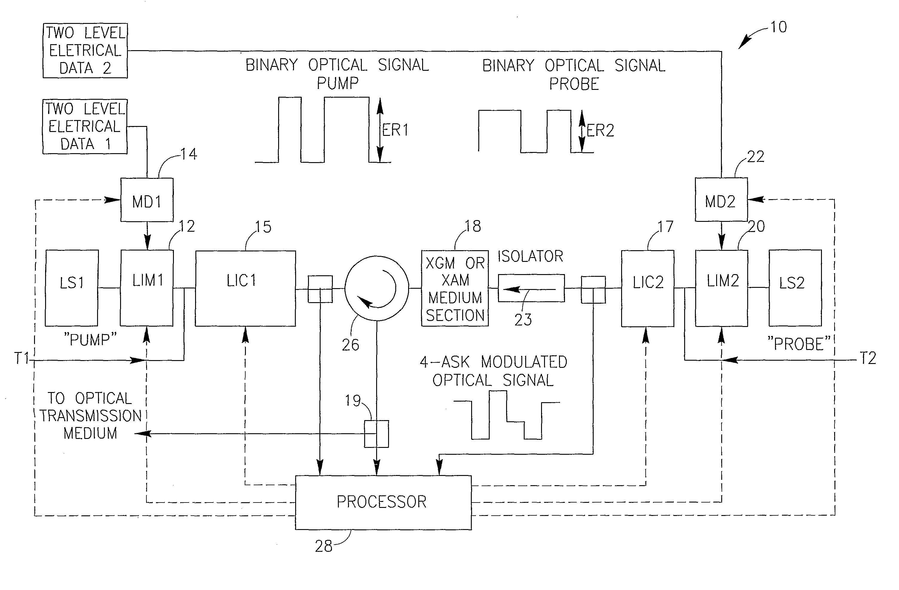
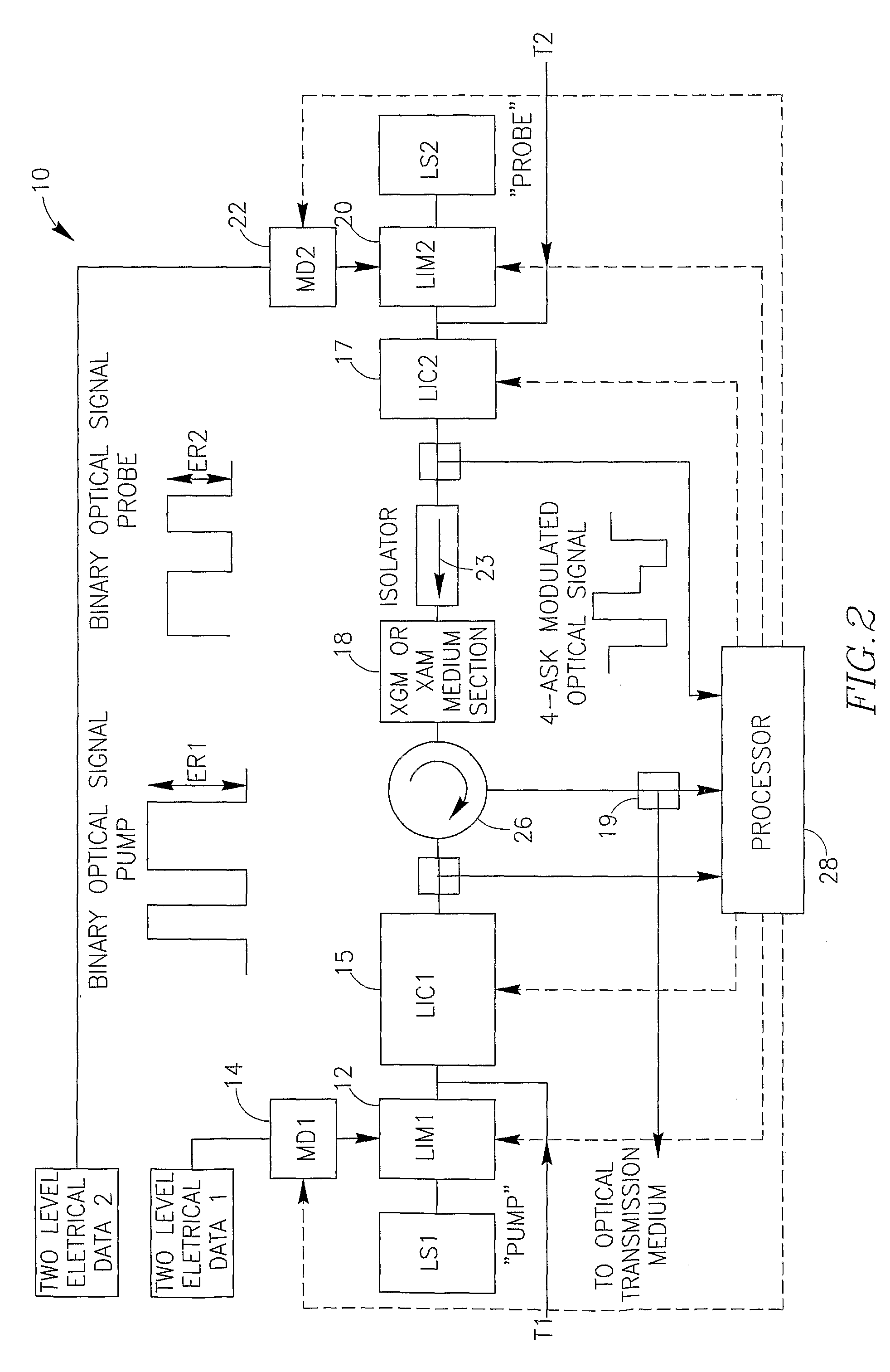
[0013]It is an object of the present invention to provide a simple though effective all-optical system, which would allow producing a required multilevel coded optical signal based on the M-ASK technology and by the minimized equipment.
[0019]It has been found by the Inventors that the modulated probe signal having a controllable ER (ER2) chosen with reference to a relevant compression factor (parameter), allows not only minimizing the required equipment for ensuring those optical levels, but also controlling and optimizing a proportion between the multiple optical levels in the obtained optical signal.
[0020]Moreover, under specific working conditions (e.g., for a plurality of specifically defined combinations of ER2, probe signal input power, and Gc / Ac values, where Gc is Gain compression parameter and Ac is Absorption compression parameter), the levels distribution and the quality of the obtained multilevel coded signal can be significantly improved in comparison with the prior art methods.
[0037]The proposed system for generating a 4-ASK optical signal from the two above-described optical signals is extremely advantageous for optical networks.
[0044]The above function allows achieving desired (optimal) gaps between multiple levels of the obtained multilevel optical signal.

Problems solved by technology

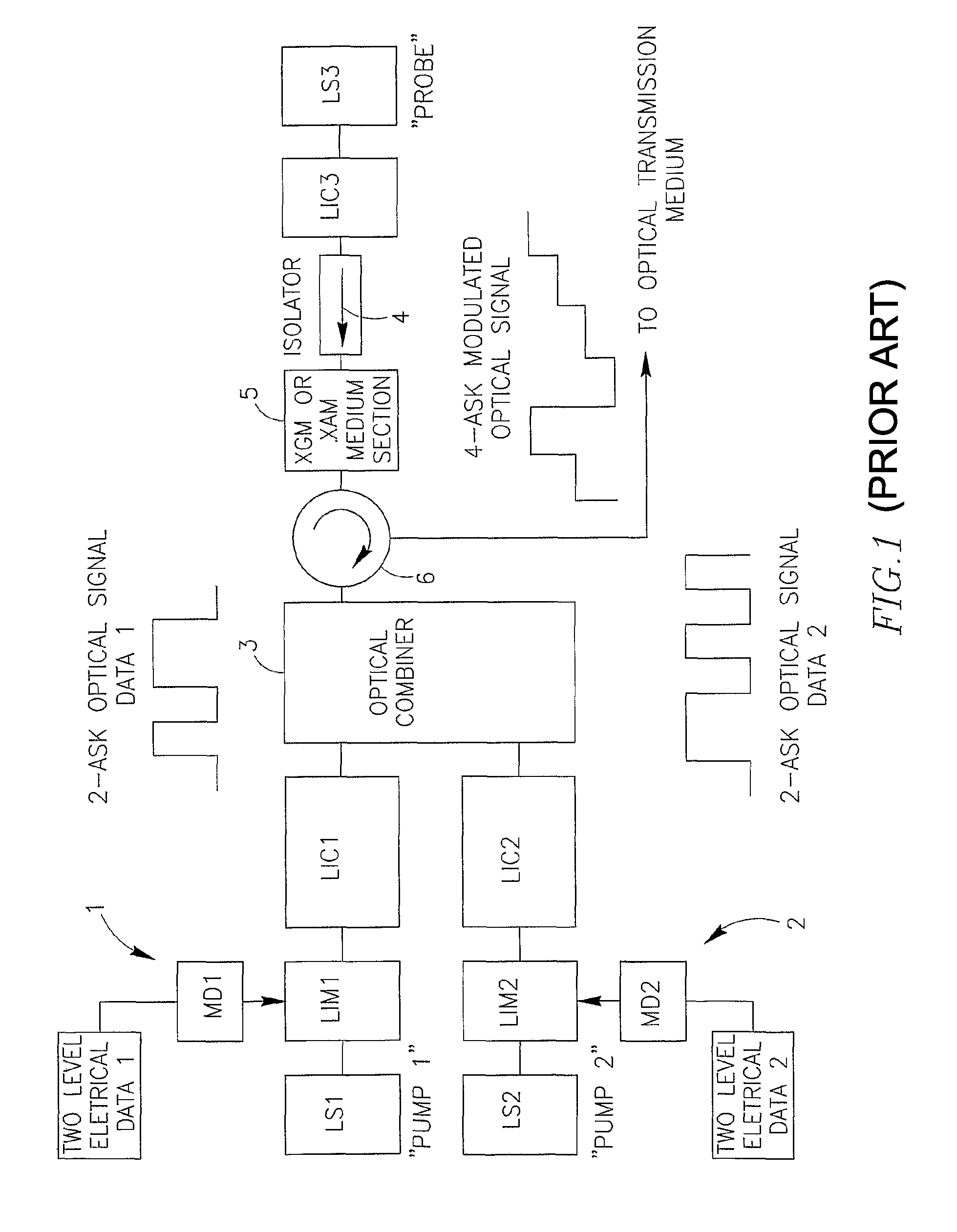
In such a configuration, moderate amplitude distortions of the electrical binary signals cause significant distortions of intermediate levels obtained in the resulting optical 4-ASK signal.
Though, to the best of the Applicant's knowledge, all-optical systems for generating a multilevel coded optical signal by using the M-ASK technology are rather complex, since they comprise multiple signal generating schemes for producing component optical signals which are to be combined for obtaining the required multilevel optical signal.

Method used


Image

  • System and method for generating multilevel coded optical signals
  • System and method for generating multilevel coded optical signals
  • System and method for generating multilevel coded optical signals

Examples


Embodiment Construction

[0086]FIG. 1 illustrates a system, which has been briefly referred to in the Background description. Two generators 1 and 2 of optical pump signals respectively comprise light sources LS1 and LS2 of two different wavelengths each modulated by two-level electrical data. Each of the two-level data is fed via a modulator driver MD1 (MD2), applied to the carrier wavelength in a light intensity modulator LIM1 (LIM2), and intensity of the two-level signal is controlled by a controller LIC1 (LIC2). The two obtained 2-ASK optical signals are combined in an optical combiner 3.

[0087]A probe optical signal LS3 generates an optical signal at yet another optical wavelength, which is regulated by a light intensity controller LIC3 and then, via an isolator 4, fed into a non-linear XAM or XGM medium section 5. In the section 5 the probe signal meets with the combined light signal applied to the section 5 via an optical circulator 6 (thus using two of three ports of the circulator).

[0088]The 4-level...


PUM


Abstract

A simple and effective all-optical system, producing a multilevel coded optical signal based on the M-ASK technology and by the minimized equipment. The novel all-optical modulation technique for optical M-ASK generation is based on nonlinear interaction between optical signals, say between N 2-ASK modulated pump signals having extinction ratio ER1 and a single 2-ASK modulated optical probe signal having extinction ratio ER2. According to the invention, a 4-ASK optical signal can be obtained using just a single binary modulated pump optical signal and a single binary modulated probe optical signal.

Description

FIELD OF THE INVENTION[0001]The present invention relates to generation of multilevel coded optical signals, more specifically to a technology using an all-optical multilevel Amplitude Shift Keying (M-ASK) modulation circuit.BACKGROUND OF THE INVENTION[0002]The increasing traffic demand in optical networks appeals for the development of novel high spectral efficiency optical modulation schemes which would lead to the better use of the available optical bandwidth while increasing the operational bit rate. Increasing the spectral efficiency can be achieved by increasing the number of symbols in a signal constellation diagram via multilevel amplitude and / or phase encoding. Non-binary modulation schemes are a mature technology in wireline and wireless Radio Frequency based systems; their deployment into optical systems has been investigated for the last years.[0003]Multilevel or M-ary amplitude shift keying (M-ASK) technologies, such as four level ASK (noted 4-ASK), offers better tolera...

Claims


Application Information

Patent Timeline
Patent Type & Authority Patents(United States)
IPC IPC(8): H04B10/00H04B10/50H04B10/54
CPCH04B10/505H04B10/541
Inventor DAHAN, DAVID JIMMYMAHLAB, URI
Owner ECE TELECOM LTD
Learn More