
Absolute capacitive micro pressure sensor

a capacitive micro-pressure sensor and capacitive technology, applied in the direction of variable capacitors, fluid pressure measurement, instruments, etc., can solve the problems of sensor drift, affecting the overall sensitivity of the pressure sensor reading or measurement, and altering the mechanical properties of the sensor, so as to improve the sensitivity of the pressure measurement reading, minimize the effect of stray capacitance and minimizing alteration

Active Publication Date: 2013-11-26
INTEGRA LIFESCI SWITZERLAND SARL
View PDF26 Cites 8 Cited by
  • Summary
  • Abstract
  • Description
  • Claims
  • Application Information

AI Technical Summary

Benefits of technology

[0017]The present invention is directed to an improved absolute capacitive micro pressure sensor that solves the aforementioned problems associated with conventional devices by minimizing stray capacitance, improving the sensitivity of pressure measurement readings, minimizing alteration of the mechanical properties of the pressure sensor membrane and minimizing formation of air bubbles in the open cavity between the base plate and deflectable membrane when the sensor is exposed to a fluid.

Problems solved by technology

Another disadvantage associated with stray capacitance is the deleterious impact on overall sensitivity of the pressure sensor readings or measurements.
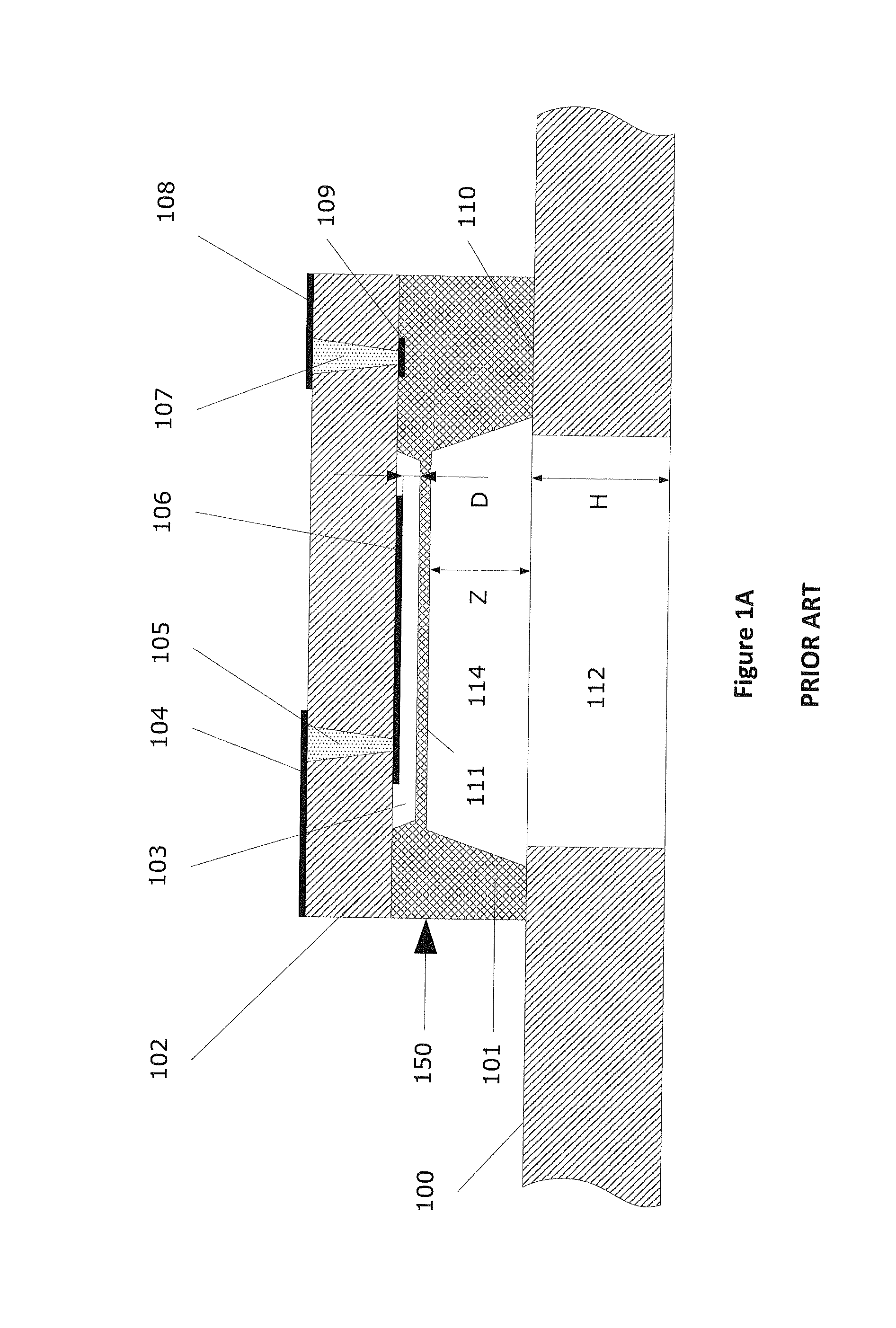
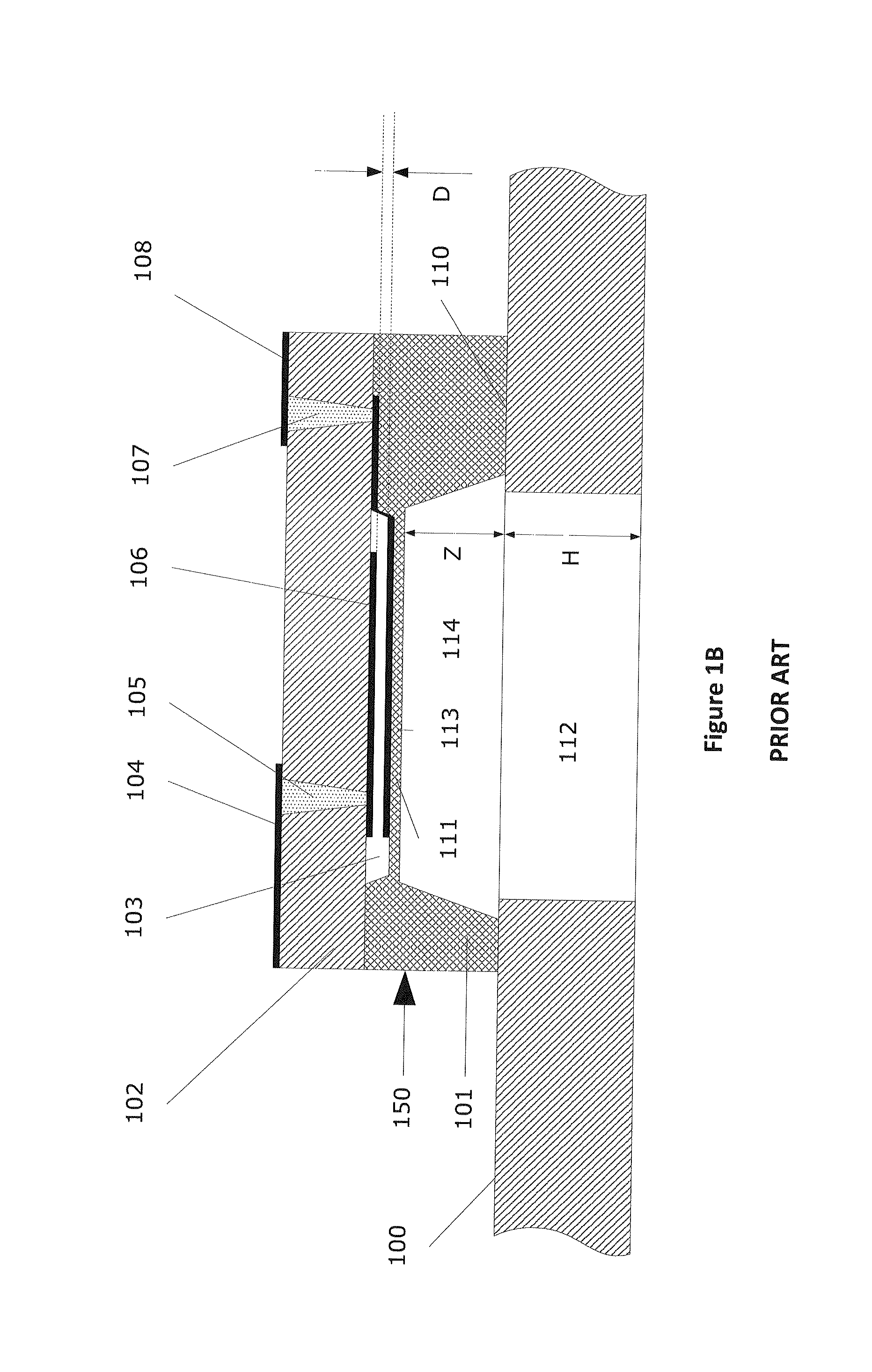
Yet another disadvantage arises from the deflectable membrane 111 of the absolute capacitive micro pressure sensor being in direct contact with a fluid over a prolonged period of time possibly altering its mechanical properties.
Etching of and / or growing a layer on the deflectable membrane 111 will undesirably alter its mechanical properties and thus result in sensor drift.
Still an additional limitation or drawback of the absolute capacitive micro pressure sensor configuration in FIGS. 1A & 1B is the reduced accuracy of the pressure measurements as a result of formation of air bubbles in the fluid.
The size constraints of the opening 112 are such that the air bubble cannot easily evacuate from the open cavity 114.

Method used


Image

  • Absolute capacitive micro pressure sensor
  • Absolute capacitive micro pressure sensor
  • Absolute capacitive micro pressure sensor

Examples


Embodiment Construction

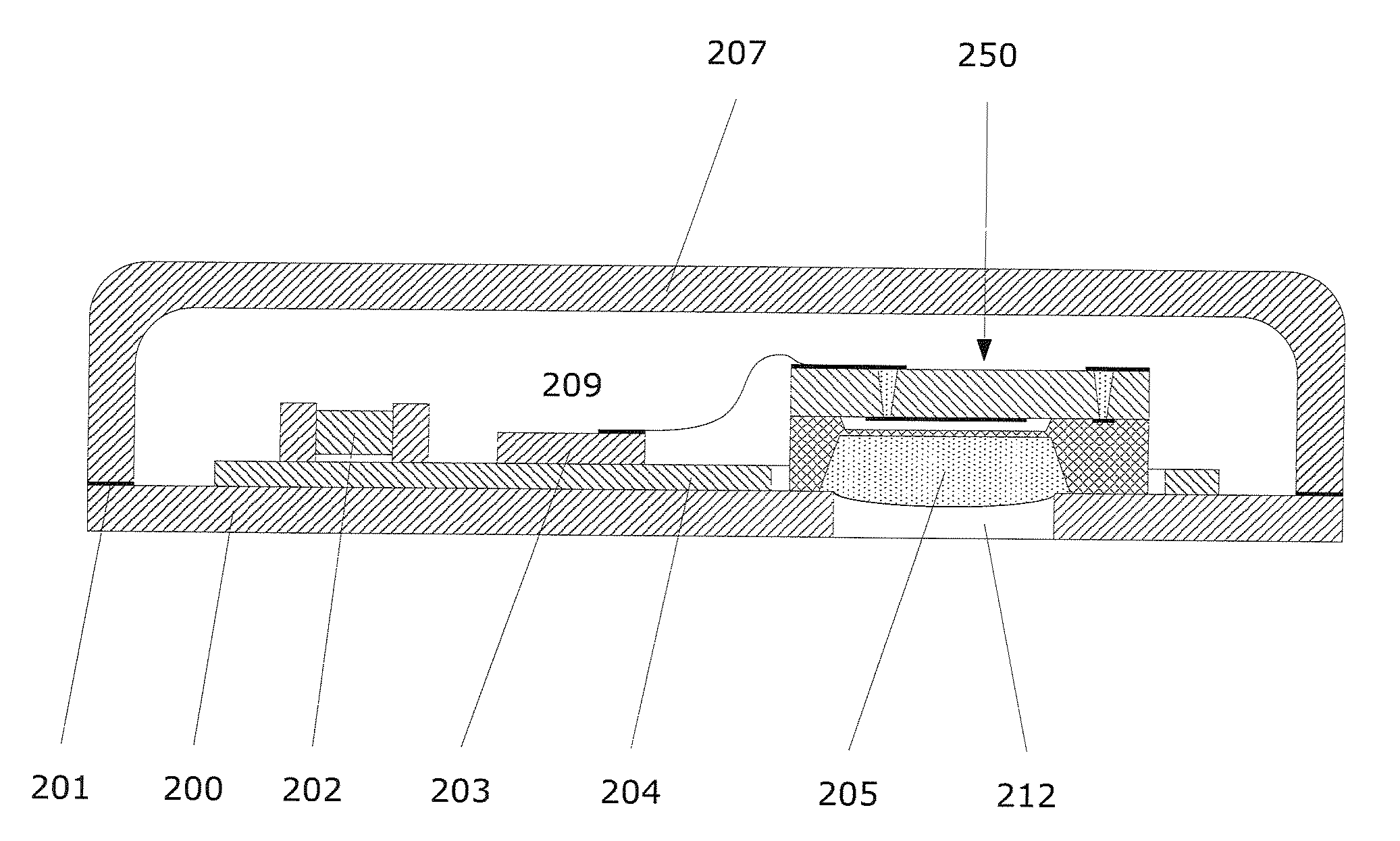
[0029]An exemplary cross-sectional view of an encapsulated absolute capacitive micro pressure sensor in accordance with the present invention is shown in FIG. 2A. A pressure sensor element 250 is disposed in a chamber 209 formed by a hermetic enclosure, capsule or packaging including a cover 207 and base plate 200, both of which are preferably made of glass. By way of illustrative purposes only, the pressure sensor element 250 shown in FIG. 2A is identical to that shown in the embodiment depicted in FIG. 1A wherein the deflectable membrane is made of a conductive material (e.g., doped p+ silicon) and serves as the second moveable capacitive electrode. Accordingly, the reference element numbers and accompanying description for the pressure sensor element components depicted in FIGS. 2A-2E are not provided. It is contemplated and within the intended scope of the present invention that the alternative pressure sensor element embodiment depicted in FIG. 1B may be substituted for pressur...


PUM

PropertyMeasurementUnit
thicknessaaaaaaaaaa
thicknessesaaaaaaaaaa

Abstract

An absolute capacitive micro pressure sensor including a pressure sensor element with a mechanically fixed electrode and a deflectable pressure sensor membrane separated from the fixed electrode by a predetermined distance. A packaging defining a chamber is formed by a cover assembled to a base plate with an opening defined therein. The chamber is filed with a fluid and / or a gas at substantially constant pressure. Within, the chamber, the pressure sensor element is mounted to the base plate to define an open cavity therebetween substantially aligned with the opening defined in the base plate. A gel is disposed in the open cavity in contact with an exposed surface of the deflectable membrane.

Description

BACKGROUND OF THE INVENTION[0001]1. Field of the Invention[0002]The present invention relates to an absolute capacitive micro pressure sensor. More particularly, the invention relates to an absolute capacitive micro pressure sensor or transducer subject to exposure to a fluid such as saline when implanted in the body.[0003]2. Description of Related Art[0004]Monocrystalline silicon absolute capacitive micro pressure sensors comprise a relatively thin silicon membrane that mechanically deflects under pressure. The mechanical deflection is correlated to the pressure to be measured. In order to measure an absolute pressure, the other side of the membrane is exposed to a substantially constant pressure created by a sealed chamber.[0005]Capacitive pressure sensors measure the mechanical deflection by measuring the change of the capacitance constituted by a dielectric region between a pair of electrodes or conductive layers, one being mechanically fixed and the other being deflectable or m...

Claims


Application Information

Patent Timeline
Patent Type & Authority Patents(United States)
IPC IPC(8): G01L7/08H01G7/00G01L9/12
CPCG01L9/0073H01L2224/48137
Inventor CRIVELLI, ROCCO
Owner INTEGRA LIFESCI SWITZERLAND SARL
Learn More