
Multi-polar feedthrough array for analog communication with implantable medical device circuitry

a medical device circuitry and multi-polar technology, applied in the direction of feed-through capacitors, coupling device connections, therapy, etc., can solve the problems of loss of hermeticity and reduce and achieve the effect of reducing the yield of imd

Active Publication Date: 2007-05-01
MEDTRONIC INC
View PDF20 Cites 43 Cited by
  • Summary
  • Abstract
  • Description
  • Claims
  • Application Information

AI Technical Summary

Benefits of technology

The invention is about improving the manufacturing of electrical feedthroughs for implantable medical devices (IMDs). The invention addresses the issue of dimensional instability of the feedthrough array which causes loss of hermeticity and reduces IMD manufacturing yields. The invention proposes an improved multi-polar feedthrough array that uses a specific metallic ferrule material for better dimensional stability. The multi-polar feedthrough array also incorporates additional pins for filtering stray electromagnetic interference (EMI) signals and analog and digital electrical communication between operative circuitry inside the IMD and external components. The invention provides a solution for reducing device volume and improving RF antenna and sensor capability in a reduced volume package. The invention also provides variable EMI filtering based on the needs of the IMD. The invention addresses the issue of dimensional instability of the feedthrough array and proposes an improved solution for manufacturing electrical feedthroughs for IMDs.

Problems solved by technology

However, as the number of discrete conductive feedthrough pins and the size of feedthrough arrays has increased while the available surface area has decreased previously acceptable dimensional instability of the array has been discovered to cause loss of hermeticity and thus, reduce IMD manufacturing yields.

Method used


Image

  • Multi-polar feedthrough array for analog communication with implantable medical device circuitry
  • Multi-polar feedthrough array for analog communication with implantable medical device circuitry
  • Multi-polar feedthrough array for analog communication with implantable medical device circuitry

Examples


Embodiment Construction

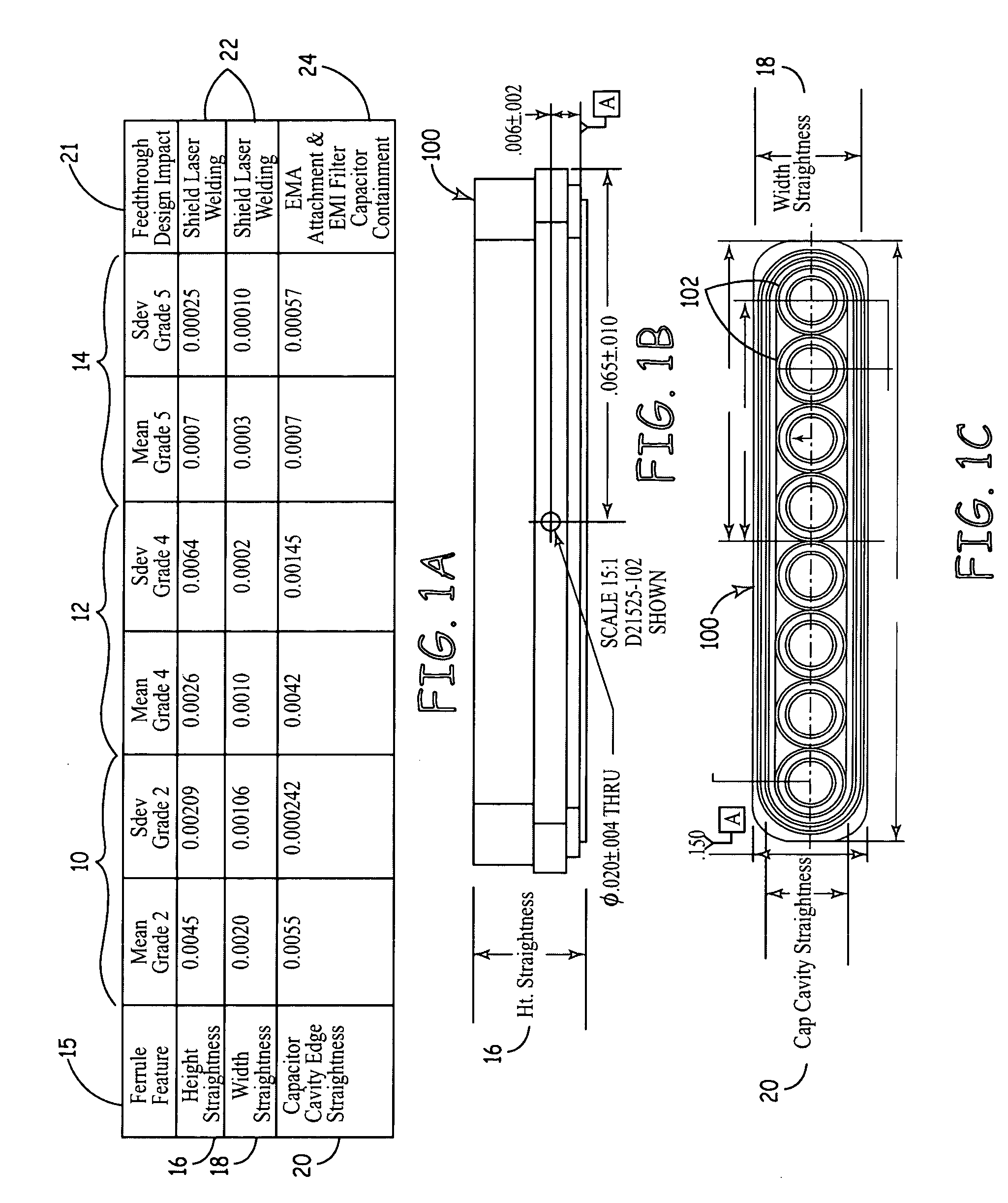
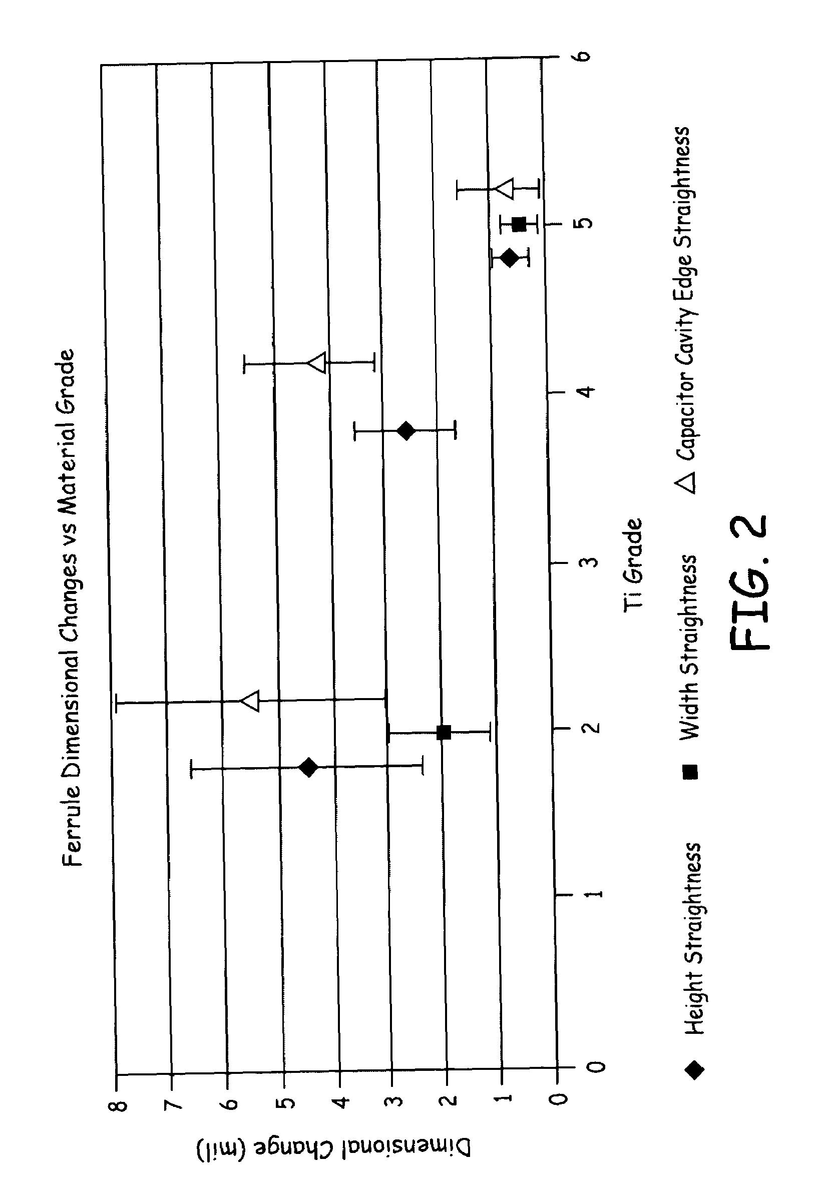
[0024]Referring now to FIG. 1A, which provides a table of empirical comparative dimensional data for grade 2 titanium (10), grade 4 titanium (12), and grade 5 titanium (14) ferrules. The departure from a desired dimension is compared in FIG. 1; namely, ferrule features 15: height straightness 16, width straightness 18 and capacitor cavity edge straightness 20. For each of the three grades of titanium the mean and standard deviation values are presented as well as the most likely negative impact of a departure from the desired dimension(s) 21. As will be apparent with reference to the rest of the disclosure herein, the inability to maintain the desired dimension(s) can unfortunately adversely affect the shield (i.e., IMD enclosure) laser welding procedures 22, EMA attachment procedures and EMI filter capacitor containment 24, among others. FIG. 1B depicts an elevational side view of an eight-hole ferrule 100 that illustrates the height straightness dimension 16, and FIG. 1C depicts a...


PUM


Abstract

An improved multi-polar feedthrough assembly employs a particular metallic ferrule material for improved dimensional stability during initial fabrication and sustained hermetic operation. In one aspect, the disclosure relates to implantable medical devices (IMDs) including an IMD enclosure fabricated with grade 2 titanium and having a ferrule material fabricated with grade 4 titanium or grade 5 titanium. In one form, the multi-polar feedthrough assembly includes a filtered feedthrough array (e.g., employing capacitive filters coupled to the electrically conductive pins or serpentine conductors of the array). According to another aspect, the improved multi-polar feedthrough assembly incorporates additional pins, thus increasing the footprint of the assembly, and the additional pins provide analog electrical communication between operative circuitry inside an IMD and analog components external to the IMD.

Description

FIELD OF THE INVENTION[0001]The present invention relates to electrical communication of signals through a conductive substrate; for example, a titanium shell of a hermetically sealed implantable medical device.BACKGROUND OF THE INVENTION[0002]Electrical feedthroughs serve the purpose of providing an electrical circuit path extending from the interior of a hermetically sealed enclosure or housing to an external point outside the enclosure. Implantable medical devices (IMDs) such as implantable pulse generators (IPGs) for cardiac pacemakers, implantable cardioverter defibrillators (ICDs), nerve, brain, organ and muscle stimulators and implantable gastric monitors, or the like, employ such electrical feedthroughs through a hermetically-sealed enclosure that surrounds operative internal circuitry and electrically couples said circuitry with external medical electrical leads and associated electrodes.[0003]Such feedthroughs typically include a ferrule adapted to fit within an opening in...

Claims


Application Information

Patent Timeline
Patent Type & Authority Patents(United States)
IPC IPC(8): H01R13/66
CPCA61N1/05A61N1/3754H01G4/35H01R13/7197A61N1/3718H01R2201/12
Inventor TAYLOR, WILLIAM J.KNOWLES, SHAWN D.OLSON, JOHN C.
Owner MEDTRONIC INC
Learn More