
LED lamp with surface area enhancing fins

a technology of surface area and led chips, applied in semiconductor devices, discharge tube main electrodes, lighting and heating apparatus, etc., can solve the problems of reduced power efficiency, inability to achieve ideal omnidirectional intensity respective to elevational or latitude coordinates, and inability to efficiently operate led chips or other solid-state lighting devices using standard 110v or 220v a.c. power, etc., to achieve adequate thermal dissipation

Active Publication Date: 2013-11-26
SAVANT TECH LLC
View PDF30 Cites 1 Cited by
  • Summary
  • Abstract
  • Description
  • Claims
  • Application Information

AI Technical Summary

Benefits of technology

The patent describes a light emitting apparatus that includes a light source and a heat sinking base element. The surface area of the apparatus is enhanced by several elements that are in thermal communication with the base element. These elements provide efficient heat dissipation without affecting the brightness of the light source. The angle of the base element is also specified within a certain range to optimize the heat dissipation capacity of the apparatus. Overall, the technical effect of the patent is to improve the heat management of light emitting apparatuses while maintaining their brightness.

Problems solved by technology

However, achieving ideal omnidirectional intensity respective to the elevational or latitude coordinate is generally not practical.
Another challenge associated with solid-state lighting is that unlike an incandescent filament, an LED chip or other solid-state lighting device typically cannot be operated efficiently using standard 110V or 220V a.c. power.
As an alternative, a series string of LED chips of sufficient number can be directly operated at 110V or 220V, and parallel arrangements of such strings with suitable polarity control (e.g., Zener diodes) can be operated at 110V or 220V a.c. power, albeit at substantially reduced power efficiency.
Yet another challenge in solid-state lighting is the need for heat sinking.
The space occupied by the heat sink blocks emitted light and hence further limits the ability to generate an omnidirectional LED-based lamp.
This limitation is enhanced when a LED lamp is constrained to the physical size of current regulatory limits (ANSI, NEMA, etc.) that define maximum dimensions for all lamp components, including light sources, electronics, optical elements, and thermal management.
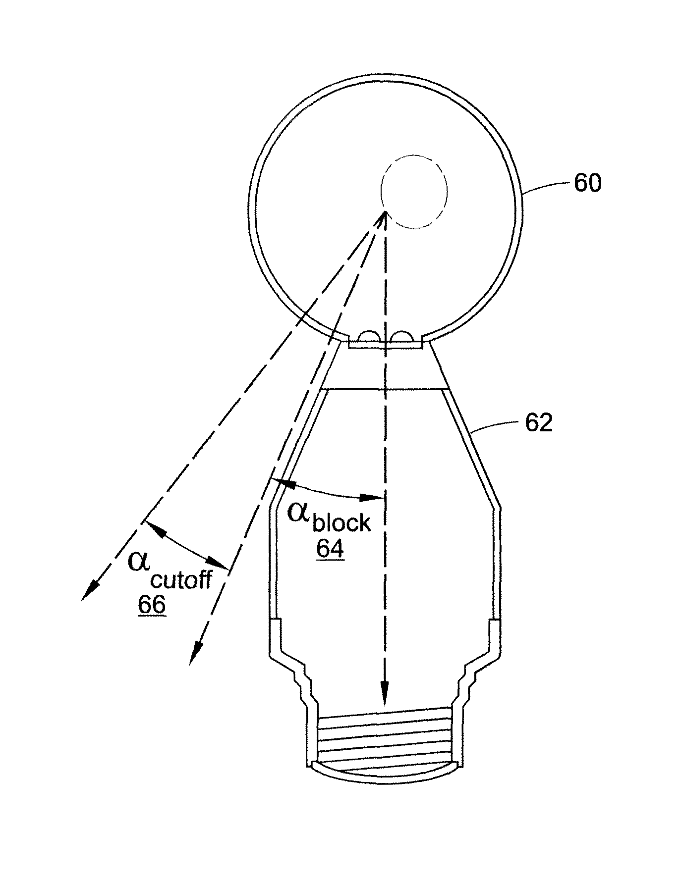
The combination of electronics and heat sinking results in a large base that blocks “backward” illumination, which has heretofore substantially limited the ability to generate omnidirectional illumination using an LED replacement lamp.
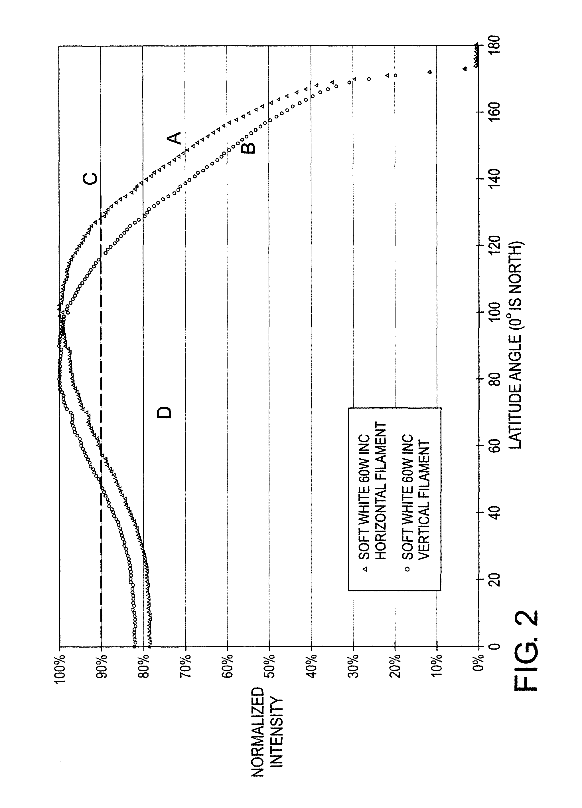
Currently, the majority of commercially available LED lamps intended as incandescent replacements do not provide a uniform intensity distribution that is similar to incandescent lamps.
Clearly, this does not provide an intensity distribution, which satisfactorily emulates an incandescent lamp.

Method used


Image

  • LED lamp with surface area enhancing fins
  • LED lamp with surface area enhancing fins
  • LED lamp with surface area enhancing fins

Examples


Embodiment Construction

[0043]The performance of an LED replacement lamp can be quantified by its useful lifetime, as determined by its lumen maintenance and its reliability over time. Whereas incandescent and halogen lamps typically have lifetimes in the range ˜1000 to 5000 hours, LED lamps are capable of >25,000 hours, and perhaps as much as 100,000 hours or more.

[0044]The temperature of the p-n junction in the semiconductor material from which the photons are generated is a significant factor in determining the lifetime of an LED lamp. Long lamp life is achieved at junction temperatures of about 100° C. or less, while severely shorter life occurs at about 150° C. or more, with a gradation of lifetime at intermediate temperatures. The power density dissipated in the semiconductor material of a typical high-brightness LED circa year 2009 (˜1 Watt, ˜50-100 lumens, ˜1×1 mm square) is about 100 Watt / cm2. By comparison, the power dissipated in the ceramic envelope of a ceramic metal-halide (CMH) arctube is ty...


PUM


Abstract

A light emitting apparatus comprising an at least substantially omnidirectional light assembly including an LED-based light source within a light-transmissive envelope. Electronics configured to drive the LED-based light source, the electronics being disposed within a base having a blocking angle no larger than 45°. A plurality of heat dissipation elements (such as fins) in thermal communication with the base and extending adjacent the envelope.

Description

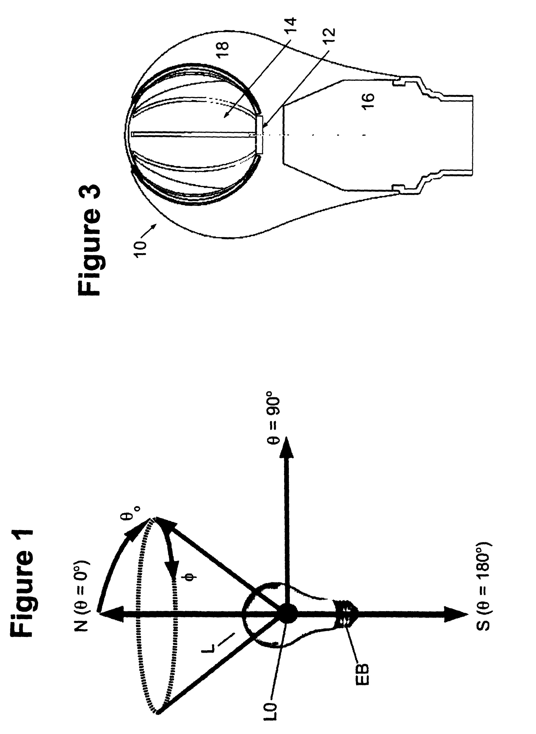
BACKGROUND[0001]The following relates to the illumination arts, lighting arts, solid-state lighting arts, and related arts.[0002]Incandescent and halogen lamps are conventionally used as both omni-directional and directional light sources. Omnidirectional lamps are intended to provide substantially uniform intensity distribution versus angle in the far field, greater than 1 meter away from the lamp, and find diverse applications such as in desk lamps, table lamps, decorative lamps, chandeliers, ceiling fixtures, and other applications where a uniform distribution of light in all directions is desired.[0003]With reference to FIG. 1, a coordinate system is described which is used herein to describe the spatial distribution of illumination generated by an incandescent lamp or, more generally, by any lamp intended to produce omnidirectional illumination. The coordinate system is of the spherical coordinate system type, and is shown with reference to an incandescent A-19 style lamp L. Fo...

Claims


Application Information

Patent Timeline
Patent Type & Authority Patents(United States)
IPC IPC(8): H01J1/02B60Q1/00
CPCF21K9/135F21V29/2212F21V29/506F21V29/74F21V29/76F21V29/77F21V29/80F21V29/75F21Y2101/02F21V29/87F21V29/86F21K9/232F21Y2115/10F21V29/78
Inventor DUDIK, DAVID C.RINTAMAKI, JOSHUA I.ALLEN, GARY R.KUENZLER, GLENN H.
Owner SAVANT TECH LLC
Learn More