Measuring method, measuring apparatus, lithographic apparatus and device manufacturing method

a technology of lithographic apparatus and measuring method, which is applied in the direction of electrical apparatus, instruments, basic electric elements, etc., can solve the problems of inherently more difficult to acquire a position accurately, limit the accuracy of position measurements that can be obtained, and the production of devices will not be cost-effective, so as to improve the accuracy of measuring the position of the substrate, the effect of prolonging the acquisition time for each individual measurement and not slowing down the operation of the alignment process

Active Publication Date: 2013-11-26
ASML NETHERLANDS BV
View PDF22 Cites 53 Cited by
  • Summary
  • Abstract
  • Description
  • Claims
  • Application Information

AI Technical Summary

Benefits of technology

[0007]According to a first aspect, the invention enables measurement of substrate position more accurately without degrading throughput of the alignment sensor. The inventors have recognized that it is possible to lengthen the acquisition time for each individual measurement, without slowing the operation of the alignment process overall.
[0013]The reduced third velocity allows a longer time for acquisition of the measured position, while the higher first velocity allows the overall throughput for a large number of position measurements to be maintained.

Problems solved by technology

The time taken for these measurements conflicts with the need to maximize throughput of the lithographic apparatus, otherwise device production will not be cost-effective.
The alignment sensors should scan the marks as quickly as possible for optimum throughput, but this need for Speed places limits on the accuracy of the position measurements that can be obtained.
It is inherently more difficult to acquire a position accurately in a short time, I addition, a measurement acquired in a short time, even if the measurement itself is perfectly accurate, will be susceptible to disturbance by dynamic positioning errors (vibrations, servo errors etc.) in the positioning of the substrate and alignment sensor.

Method used


Image

  • Measuring method, measuring apparatus, lithographic apparatus and device manufacturing method
  • Measuring method, measuring apparatus, lithographic apparatus and device manufacturing method
  • Measuring method, measuring apparatus, lithographic apparatus and device manufacturing method

Examples


Embodiment Construction

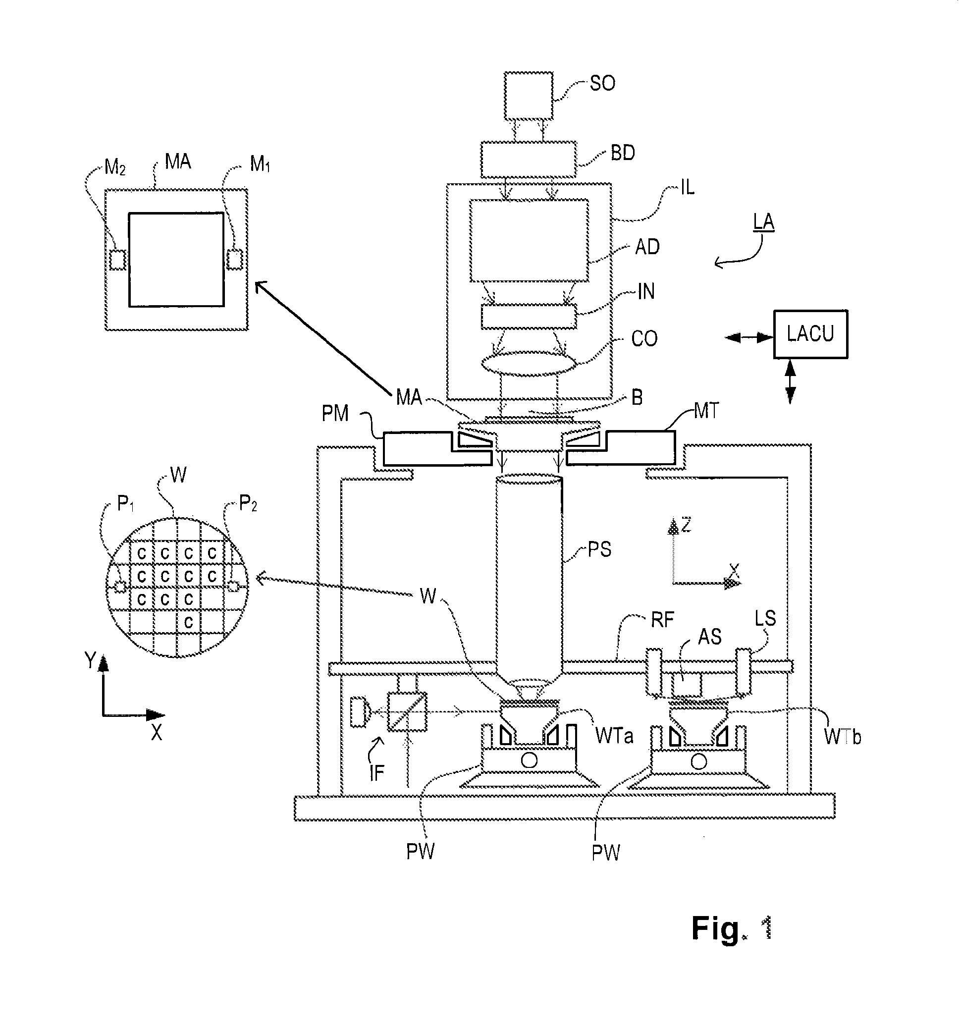
[0033]FIG. 1 schematically depicts a lithographic apparatus according to one embodiment of the invention. The apparatus comprises:[0034]an illumination system (illuminator) IL configured to condition a radiation beam B (e.g. UV radiation or EUV radiation).[0035]a support structure (e.g. a mask table) MT constructed to support a patterning device (e.g. a mask) MA and connected to a first positioner PM configured to accurately position the patterning device in accordance with certain parameters;[0036]a substrate table (e.g. a wafer table) WTa or WTb constructed to hold a substrate (e.g. a resist-coated wafer) W and connected to a second positioner PW configured to accurately position the substrate in accordance with certain parameters; and[0037]a projection system (e.g. a refractive projection lens system) PS configured to project a pattern imparted to the radiation beam B by patterning device MA onto a target portion C (e.g. comprising one or more dies) of the substrate W.

[0038]The i...


PUM


Abstract

An apparatus (AS) measures positions of marks (202) on a lithographic substrate (W). A measurement optical system comprises illumination subsystem (504) for illuminating the mark with a spot of radiation (206) and as detecting subsystem (580) for detecting radiation diffracted by the mark. The substrate and measurement optical system move relative to one another at a first velocity (vW) so as to scan the mark while synchronously moving the spot of radiation relative to the reference frame (RF) of the measurement optical system at a second velocity (vSPOT). The spot scans the mark at a third velocity (vEFF) which is lower than the first velocity to allow more time for accurate position measurements to be acquired. In one embodiment, an objective lens (524) remains fixed in relation to the reference frame while a moving optical element (562) imparts the movement of the radiation spot relative to the reference frame.

Description

CROSS REFERENCE TO RELATED APPLICATIONS[0001]This application is related to U.S. Provisional Patent Application No. 61 / 444,373, filed Feb. 18, 2011, and to U.S. Provisional Patent Application No. 61 / 468,208, filed Mar. 28, 2011, which are incorporated by reference herein in their entirety.BACKGROUND[0002]1. Field of Invention[0003]The invention relates in general to a measuring method, a lithographic apparatus, a substrate and a method for manufacturing a device.[0004]2. Related Art[0005]A lithographic apparatus is a machine that applies a desired pattern onto a substrate, usually onto a target portion of the substrate. A lithographic apparatus can be used, for example, in the manufacture of integrated circuits (ICs). In that instance, a patterning device, which is alternatively referred to as a mask or a reticle, may be used to generate a circuit pattern to be formed on an individual layer of the IC. This pattern can be transferred onto a target portion (e.g. comprising part of, on...

Claims


Application Information

Patent Timeline
Patent Type & Authority Patents(United States)
IPC IPC(8): G01B11/14G01B11/00
CPCG02B21/0048G01B11/14G01B11/00G03F9/7088G02B26/105H01L21/0273H01L21/0274G03F7/70625
Inventor DEN BOEF, ARIE JEFFREYBEEMS, MARCEL HENDRIKUS MARIACADEE, THEODORUS PETRUS MARIALAFARRE, RAYMOND WILHELMUS LOUIS
Owner ASML NETHERLANDS BV
Why Eureka
Try Eureka