Marine seismic surveying in icy or obstructed waters

a technology of ice or obstructed waters and seismic surveying, which is applied in the field of marine seismic surveying, can solve the problems of prone to damage, difficult to produce seismic records, and expensive, and achieves the effects of reducing the risk of accidents, reducing the safety of the vessel, and increasing the difficulty of towing the source and streamer

Active Publication Date: 2013-11-26
NUTEC SCI
View PDF137 Cites 31 Cited by
  • Summary
  • Abstract
  • Description
  • Claims
  • Application Information

AI Technical Summary

Benefits of technology

[0006]A marine seismic surveying apparatus has a skeg that mounts on a vessel and preferably on the vessel's aft or stern. The skeg's distal end extends below the vessel's waterline and can even extend several meters below the vessel's keel. A seismic surveying system deploys from the vessel and has a number of cables for streamers and cables for a seismic source, such as an air gun array. To protect these cables, a channel in the skeg's after edge holds the cables and directs them below the vessel's waterline. In this way, surface ice cannot interfere with the cables while the seismic surveying system is being towed.
[0007]The skeg's distal end has tow points, which can be provided on a base. Towlines for the system's streamers and source connect to these tow points. In this way, these towlines deploy under the water and away from any ice floes that may be present at the water's surface.
[0008]In the towed survey system behind the vessel, a floatation device can support a horizontally arrayed source. Preferably, this device floats below the water's surface to avoid ice floes. Alternatively, a vertical source can be used from the skeg. When operating this vertical source, the firing of the source elements or guns can be timed to account for any tilt that the vertical source has. This timed firing can maintain the fidelity of the sources and keep a downward facing characteristic of the seismic source signal produced.
[0010]To facilitate locating the streamers and sensors for the survey, these controllable vehicles can be intermittently brought to the surface when clear of ice floes or other obstructions so that GPS readings can be obtained and communicated to a control system. After obtaining the GPS readings, the controllable vehicles can float back under the surface. An Inertial Navigation System (INS) device, integrated navigation system, or other system can be used to supplement the GPS readings so the location of the streamers can be determined even when significant ice floes at the surface prevent the controllable vehicles from obtaining GPS readings.
[0011]When performing the marine seismic surveying, an ice-breaking vessel or the tow vessel itself may break pack ice ahead of the towed streamers and source. In the disclosed system, Ice impact events against the hull of the ice-breaking vessel are detected and recorded while the streamers and source are being towed. At the same time, seismic signals from the source are generated, and the sensors on the streamers detect seismic energy, which is recorded as part of the seismic record for the survey. Using information about the recorded impact events, the data in the seismic record resulting from those events can then be filtered out of the seismic record, allowing operators to analyze the seismic data relatively free of data from the ice impact events. Alternatively, the known information about the impact events can be isolated from the seismic record and can be mathematically modeled as high fidelity sources of seismic data for analysis.

Problems solved by technology

Marine locations covered by ice, debris, large swells, or other obstacles can make surveying more difficult, expensive, or even impossible.
The noise generated by ice impacts can complicate the seismic record produced.
Additionally, the ice floes on the water's surface make towing the source and streamers more difficult and prone to damage.
For example, any components of the system at the water's surface can encounter ice, become bogged down, and lost.
Likewise, ice pulled under the hull and rising behind the vessel can shear away these cables and lines.

Method used


Image

  • Marine seismic surveying in icy or obstructed waters
  • Marine seismic surveying in icy or obstructed waters
  • Marine seismic surveying in icy or obstructed waters

Examples


Embodiment Construction

[0054]A. Marine Seismic Survey System

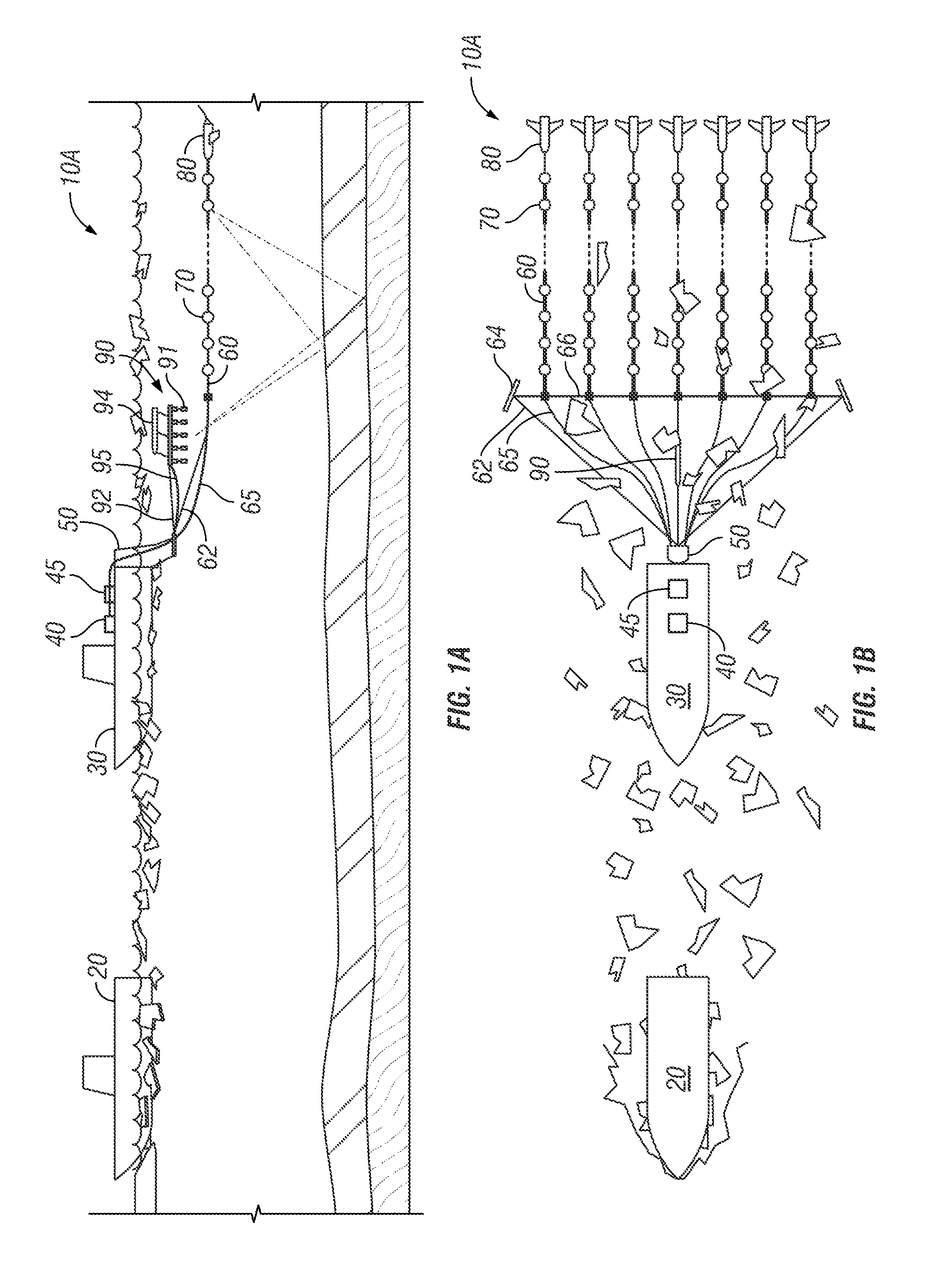
[0055]A marine seismic survey system 10A in FIGS. 1A-1B can be used in icy regions having glacial ice, pack ice, and ice floes. However, elements of the system 10A can be used in other locations having debris, plants, flotsam, jetsam, or other obstructions or obstacles at the water's surface that can interfere with towed components of the marine seismic survey system.

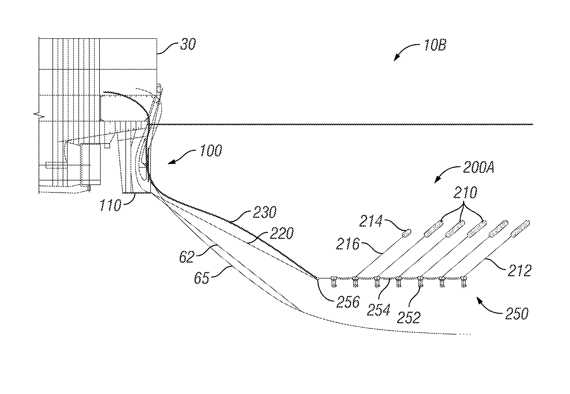
[0056]For icy regions, the system 10A preferably includes an icebreaker vessel 20 that breaks ice in advance of a tow vessel 30. In operation, the icebreaker vessel 20 breaks pack ice and diverts ice floes to create a tract for passage of the tow vessel 30. As the tow vessel 30 tows one or more streamers 60, a supply system 45 operates a source 90, and a control system 40 having a seismic recorder records the seismic data obtained with sensors 70 on the streamers 60.

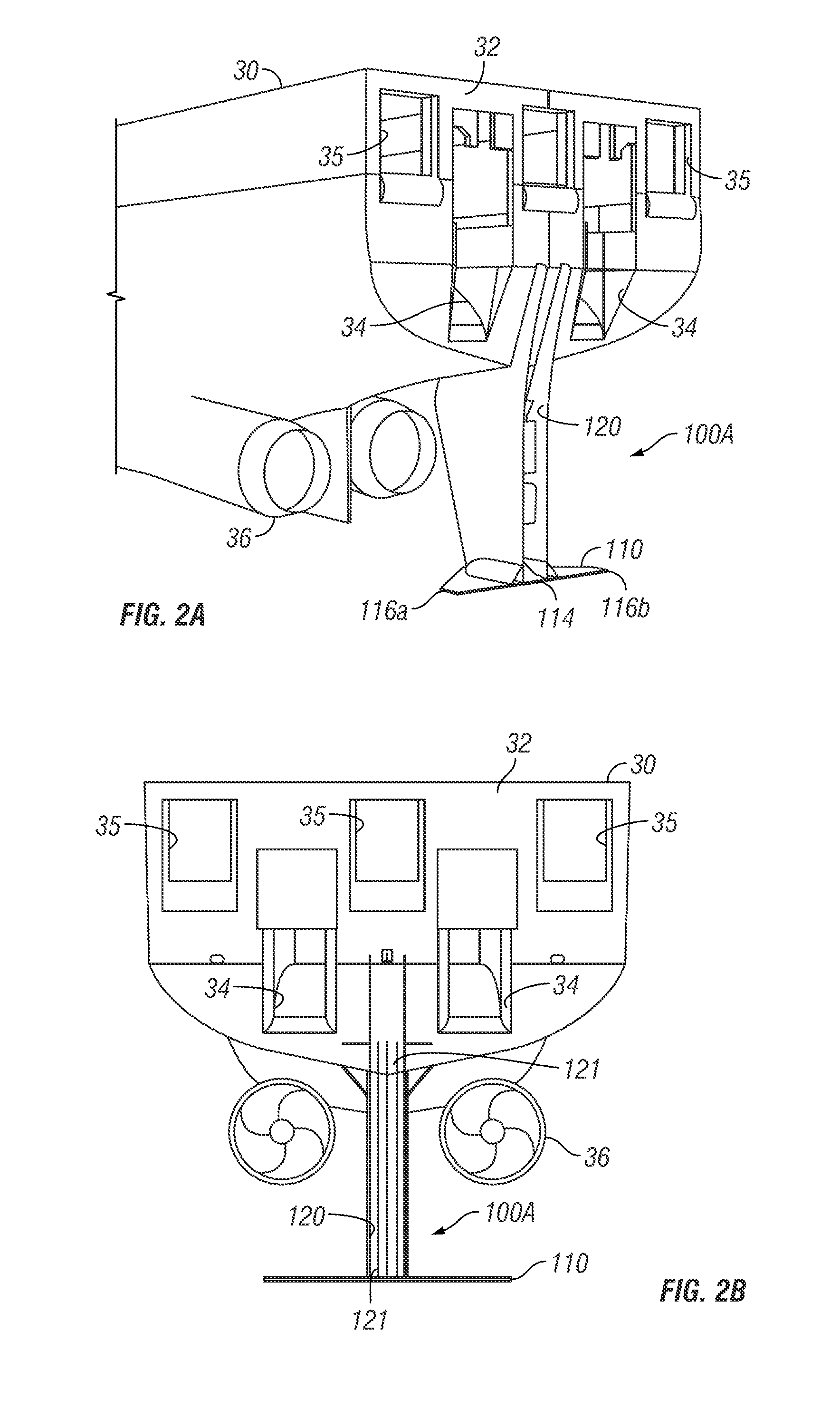
[0057]Because the tow vessel 30 operates in icy or obstructed waters, a protective device 50 on the tow vessel 30 coupl...


PUM


Abstract

A skeg mounts from the stern of a towing vessel and extends below the waterline. A channel in the skeg protects cables for steamers and a source of a seismic system deployed from the vessel. Tow points on the skeg lie below the water's surface and connect to towlines to support the steamers and source. A floatation device supports the source and tows below the water's surface to avoid ice floes. The streamers can have vehicles deployed thereon for controlling a position on the streamer. To facilitate locating the streamers, these vehicles on the streamers can be brought to the surface when clear of ice floes so that GPS readings can be obtained and communicated to a control system. After obtaining readings, the vehicles can be floated back under the surface. Deploying, using, and retrieving the system accounts for ice at the surface in icy regions. In addition, handling the seismic record can account for noise generated by ice impact events.

Description

CROSS-REFERENCE TO RELATED APPLICATIONS[0001]This is a non-provisional of U.S. Prov. Appl. Nos. 61 / 158,698, filed 9 Mar. 2009 and entitled “Marine Seismic Surveying in Icy Waters; 61 / 246,367, filed 28 Sep. 2009 and entitled “Floatation Device for Marine Seismic Surveying in Icy Waters;” and 61 / 261,329, filed 14 Nov. 2009 and entitled “Marine Seismic Surveying in Icy or Obstructed Waters,” which are each incorporated herein by reference in their entireties and to which priority is claimed.BACKGROUND[0002]Conventional marine seismic surveying uses a seismic source and a number of streamers towed behind a seismic survey vessel. These streamers have sensors that detect seismic energy for imaging the formations under the seafloor. Deploying the streamers and sources and towing them during a survey can be relatively straightforward when operating in open waters with moderate swells or the like.[0003]Marine locations covered by ice, debris, large swells, or other obstacles can make surveyi...

Claims


Application Information

Patent Timeline
Patent Type & Authority Patents(United States)
IPC IPC(8): G01V1/38B63B3/38B63B35/08B63B21/66
CPCG01V1/38B63B3/38B63B21/66B63B35/08G01V1/3843B63B3/14B63B21/663B63B2211/06B63B3/70B63B43/18G01V1/3826G01V1/3835
Inventor GAGLIARDI, JOSEPH R.RICE, SHAWNSCHNEIDER, CURTCUNKELMAN, JEFFREY W.DUDLEY, TIMOTHY A.LAMBERT, DALEBURNHAM, MIKE
Owner NUTEC SCI
Why Eureka
Try Eureka