
Gate arm saver

a technology of safety devices and cams, which is applied in the direction of traffic gates, ways, applications, etc., can solve the problems of complex arrangements, its pivot mechanism, and damage to the gate arm, so as to reduce the risk of theft, the cam profile is easy to machine, and the effect of reducing the risk of th

Inactive Publication Date: 2013-12-10
SIEMENS MOBILITY INC
View PDF23 Cites 3 Cited by
  • Summary
  • Abstract
  • Description
  • Claims
  • Application Information

AI Technical Summary

Benefits of technology

[0008]It has been found that the provision of a detent, in the form of a notch and cam, allows the setting of the force threshold to be overcome by simply varying the depth of the notch. The notch may be easily machined into the profile of the cam. The opening motion of the arm may also be controlled at least in part by the profile of the cam and or the profile of the notch.
[0009]Significant advantages may result from embodiments of the invention. The use of the leaf spring makes the design less expensive than current arm savers and the design is less susceptible to vandalism as it has fewer moving parts and is more robust. The design will also avoid the need for complicated loading arrangements used in current arm savers and makes the design safer to install and maintain.

Problems solved by technology

On occasions gate-arms are damaged when vehicles collide with them.
This causes damage to the gate arm and its pivot mechanism.
The arrangements are complicated, only permit a small range of movement and may be subject to failure as it will be appreciated that gate-arms are located in the open and thus exposed to the effects of the weather.
In remote areas, it can take some time for these resources to arrive to conduct these resetting operations.

Method used


Image

  • Gate arm saver
  • Gate arm saver
  • Gate arm saver

Examples


Embodiment Construction

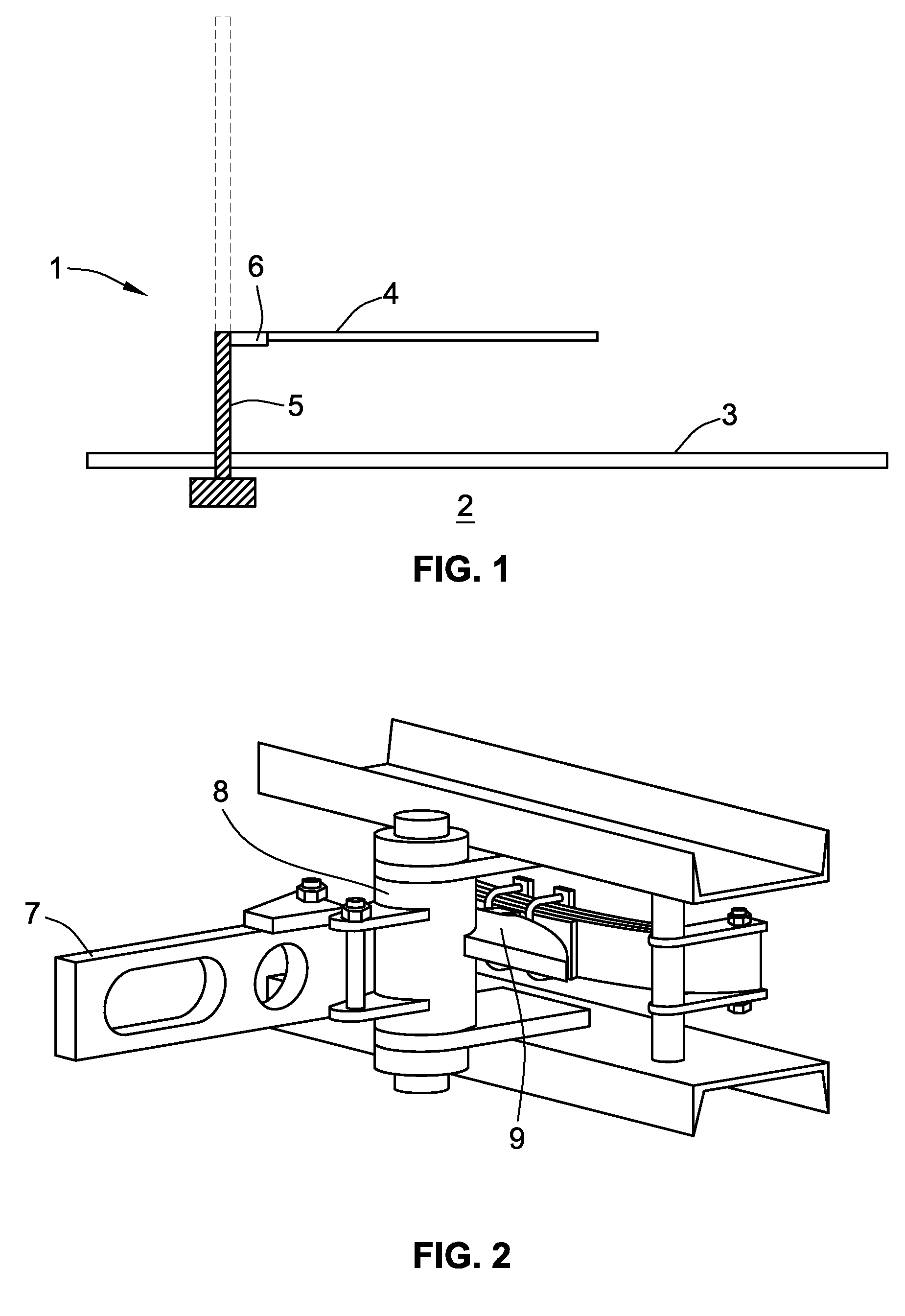
[0016]As is shown in FIG. 1, a rail road gate 1 is positioned at an approach 2 to a rail road crossing point 3. The gate 1 includes a gate arm 4 which may be lowered from a vertical position (shown in broken outline) to a horizontal deployed position. In the deployed position, the arm 4 forms a barrier to prevent road traffic crossing the rail road.

[0017]The gate arm 4 is connected to a lifting device 5 by a gate saver 6. The gate saver 6 is shown in greater detail in FIG. 2 with the gate arm removed. The gate arm fits over a gate arm mounting bracket 7. The gate arm mounting bracket is connected to a pivot 8 that defines a pivot axis 20 and about which is fixed a cam 9.

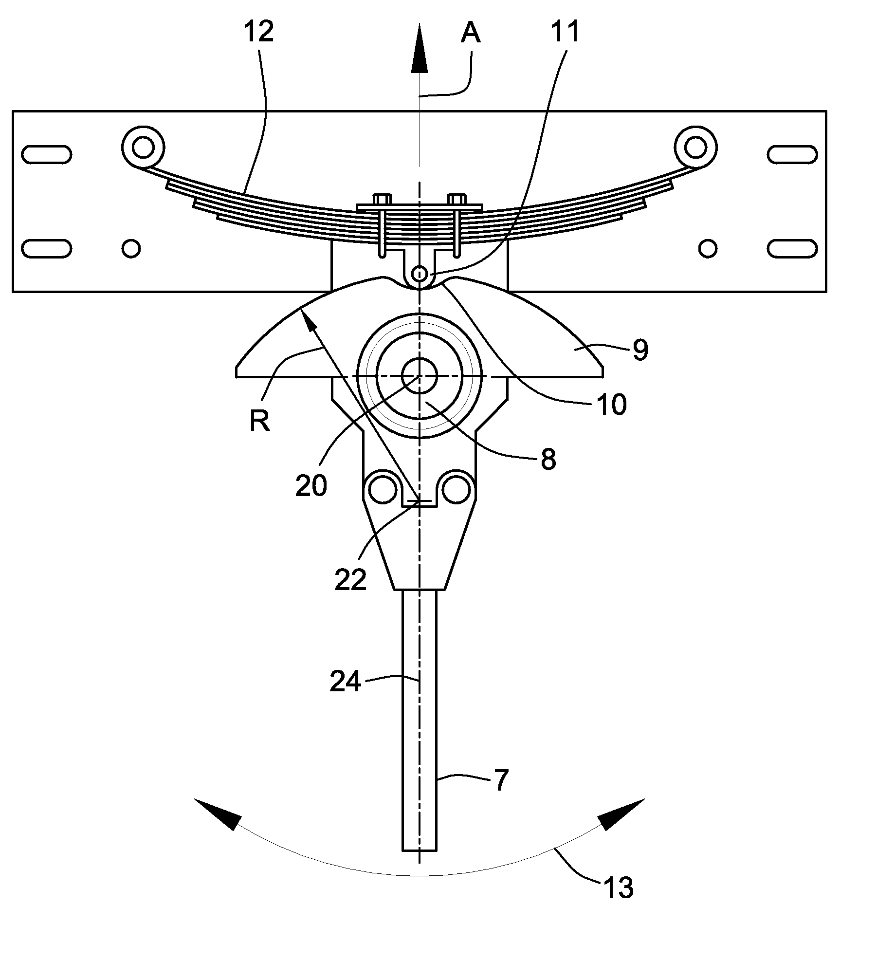
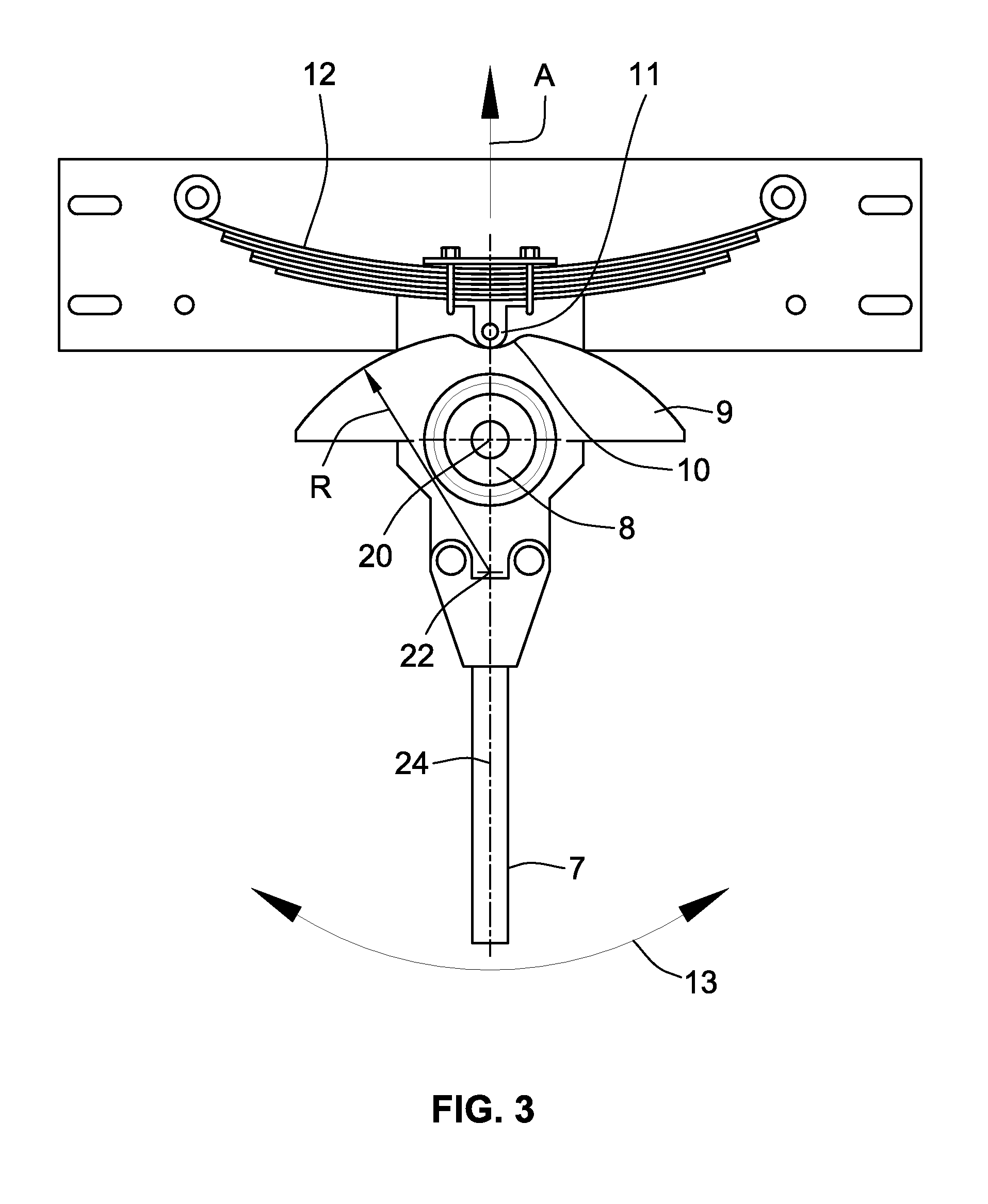
[0018]As is more clearly shown in FIG. 3, the cam 9 is generally arcuate in plan with a radius of curvature R having an origin 22 with a semi-circular notch 10 at its apex. Within the notch 10 is located a cam follower 11. The cam follower 11 is urged into engagement with the notch 10 by a leaf-spring 12. The notch 1...


PUM


Abstract

A gate arm saver is provided. The gate arm saver includes a cam and cam follower arrangement. A biasing element biases the cam follower into engagement with a detent formed in the cam upon rotation of the cam from a rest position due a loading placed upon a gate arm extending from the gate arm saver.

Description

FIELD OF THE INVENTION[0001]This invention generally relates to rail road safety technology and more particularly, but not exclusively, to railroad safety devices for use in a rail road system at a level crossing.BACKGROUND OF THE INVENTION[0002]Road traffic is prevented from crossing a rail road by a barrier or gate arm. The gate arm is lowered from a raised to a substantially horizontal position to present a physical barrier.[0003]On occasions gate-arms are damaged when vehicles collide with them. This causes damage to the gate arm and its pivot mechanism. To alleviate this problem so-called gate savers are available. These allow the gate arm to pivot in a horizontal plane. In order to restore the gate arm to its original position it is known to provide hydraulic pistons or compression springs. The arrangements are complicated, only permit a small range of movement and may be subject to failure as it will be appreciated that gate-arms are located in the open and thus exposed to th...

Claims


Application Information

Patent Timeline
Patent Type & Authority Patents(United States)
IPC IPC(8): B61L29/04
CPCB61L29/04E01F13/06
Inventor DEITCHMAN, JERRY C.
Owner SIEMENS MOBILITY INC
Learn More