Optical element and light source comprising the same

a technology of optical elements and light sources, applied in the field of light design, can solve the problems of increasing the overall cost of the overall device, the danger of burning objects that come into contact with glass bulbs, and the relatively short life span of incandescent light sources, and achieve the effect of easy manufacturing and low cos

Active Publication Date: 2013-12-10
KONINK PHILIPS ELECTRONICS NV
View PDF14 Cites 18 Cited by
  • Summary
  • Abstract
  • Description
  • Claims
  • Application Information

AI Technical Summary

Benefits of technology

[0006]In view of the above, it is an object of the present invention to provide an optical element capable of emitting light having a light intensity distribution similar to an incandescent light source, which optical element has a low cost and allows for easier manufacturing in comparison with conventional devices.
[0007]It is another object of the present invention to provide a LED light source having a light intensity distribution similar to an incandescent light source, which light source has a low cost and allows for easier manufacturing in comparison with conventional devices.

Problems solved by technology

However, the life span of incandescent light sources is typically relatively short, usually limited to the life span of the filament.
In addition, the glass bulb generally becomes very hot due to the high temperature of the filament, presenting a potential danger of burning objects that come into contact with the glass bulb.
However, most LEDs are only capable of emitting light into a hemisphere (solid angle 2π sr), whereas incandescent light sources employing a glowing filament generally emits light uniformly into a full sphere (solid angle 4π sr).
However, such reflective foils or coatings may increase the cost of the overall device in that additional material as well as additional manufacturing steps may be required.

Method used


Image

  • Optical element and light source comprising the same
  • Optical element and light source comprising the same
  • Optical element and light source comprising the same

Examples


Embodiment Construction

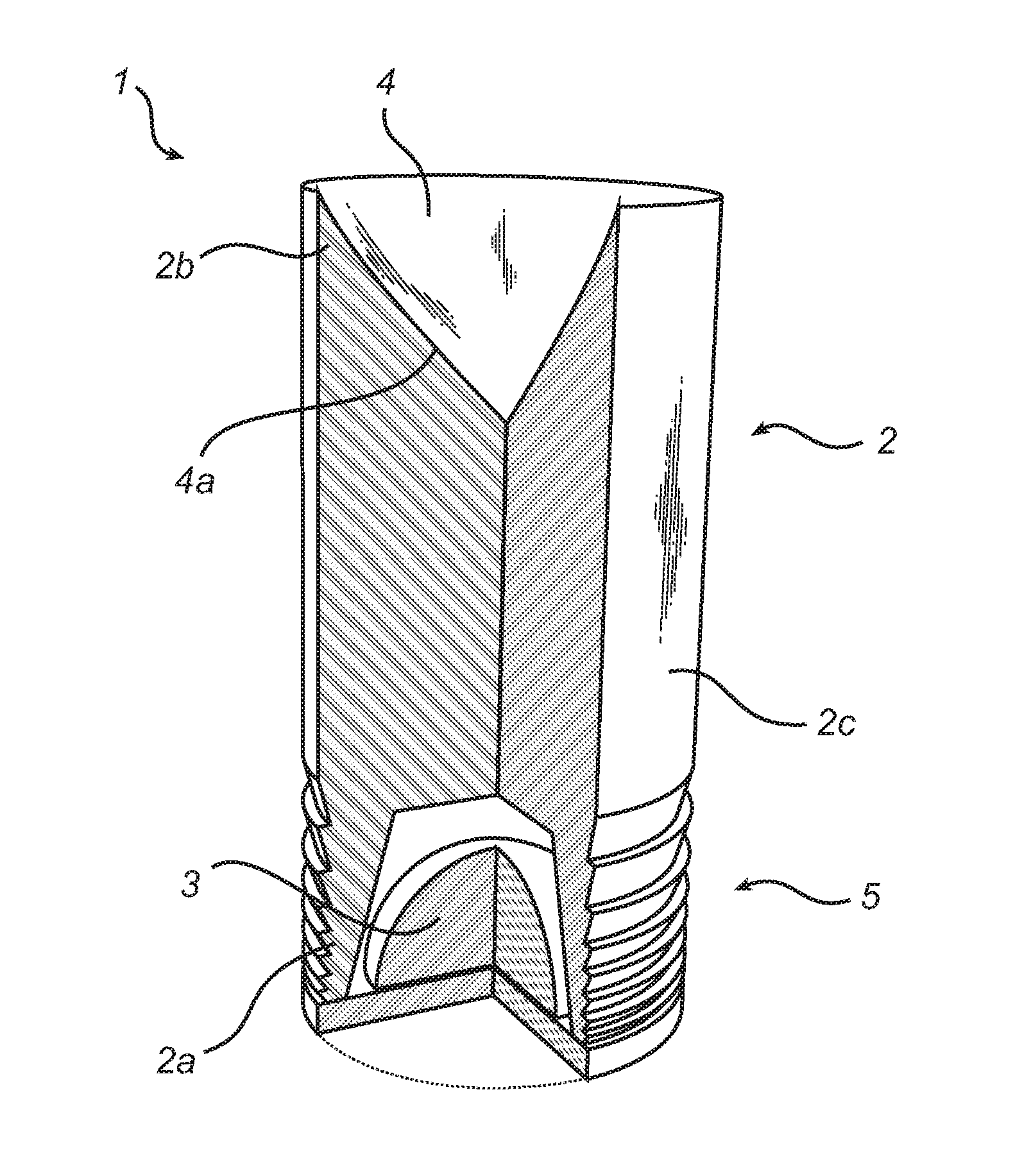
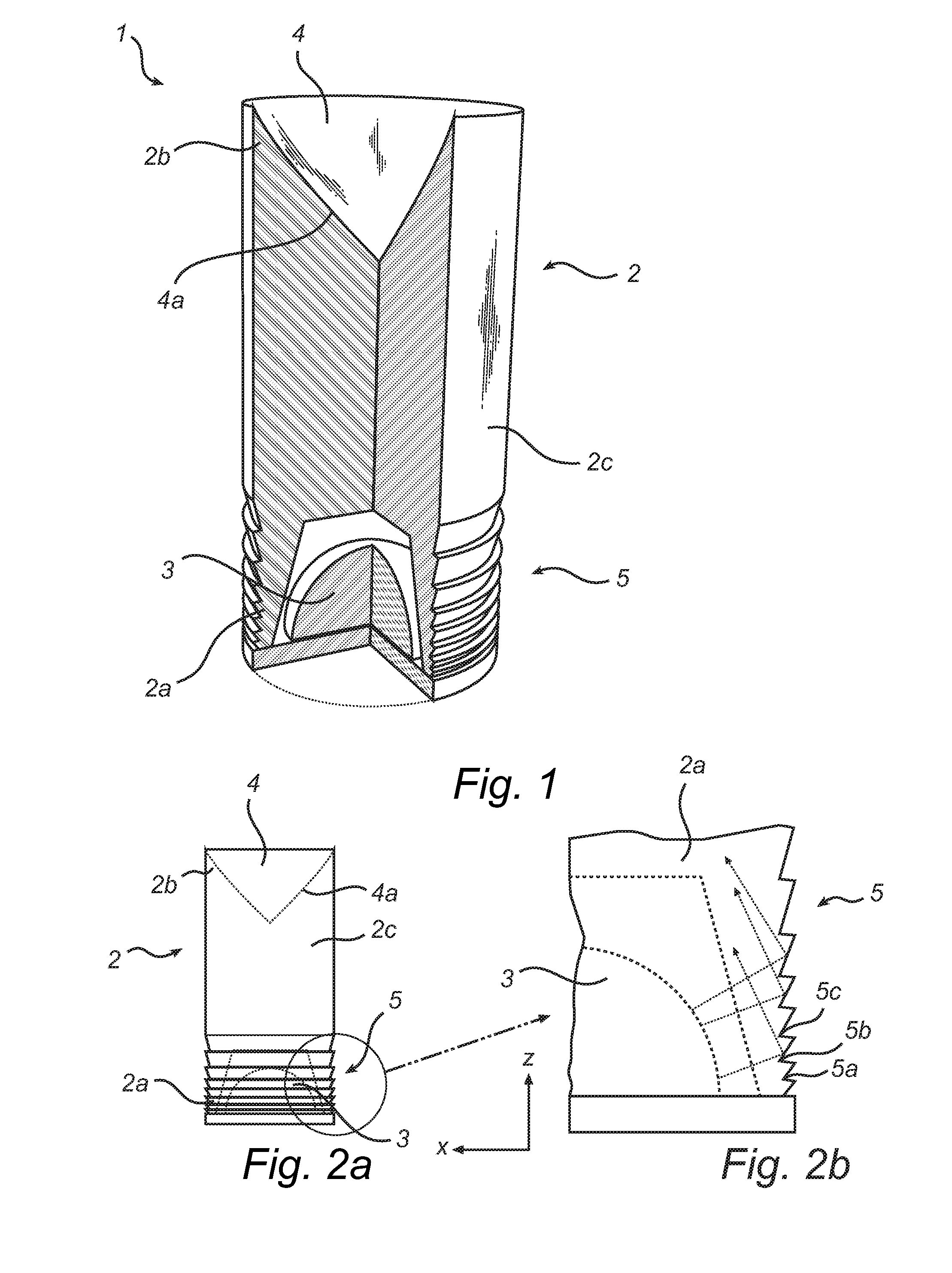
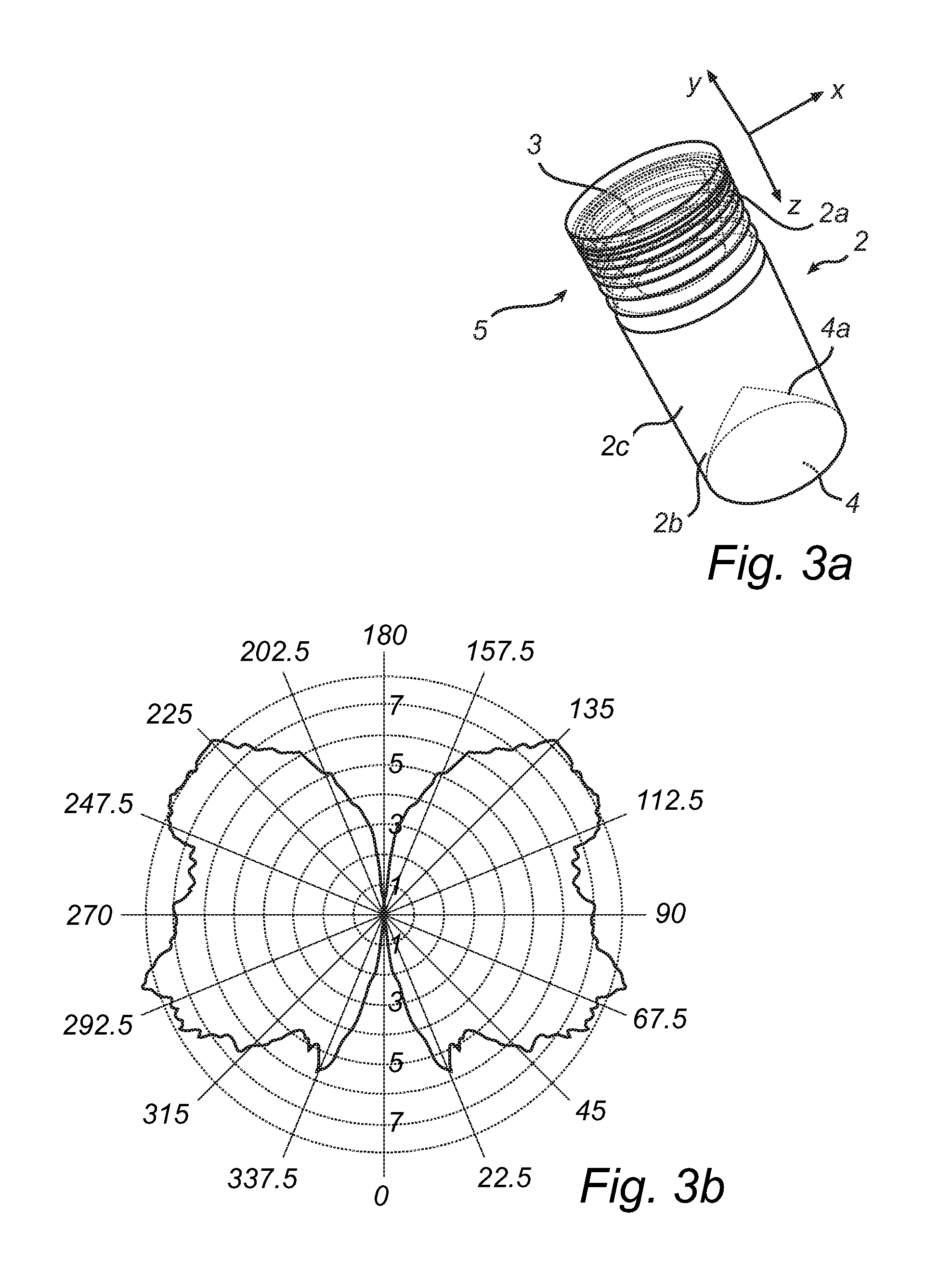
[0039]FIG. 1 is a schematic sectional view illustrating an exemplary embodiment of the present invention, wherein the optical element 1 comprises a light transmissive light guide 2 extending along an axial direction (the z-axis), the light guide 2 having an input end 2a, an output end 2b, and a central region 2c therebetween. The optical element 1 further comprises a light unit 3 comprising one or more LEDs, in this particular case a single large-sized LED, such as an Acriche LED from Seoul Semiconductors, and a reflector 4 having a reflective surface 4a facing the output end 2b of the light guide 2. The reflecting surface 4a thereby has a normal (not shown) directed towards the output end 2b of the light guide 2. According to the illustrated example, the reflective surface 4a is arranged such that at least a portion of the reflective surface 4a is concave, that is curving inwards into the light guide 2 (generally towards the input end 2a). As illustrated in FIG. 1, the light guide ...


PUM


Abstract

The present invention relates to an optical element including a light guide, into which light from one or more light-emitting diodes in a light unit arranged at one end of the light guide is injected, and a reflector arranged at the other end of the light guide capable of reflecting light incident on the reflector. The light guide further includes a prismatic surface comprising a plurality of prisms, each prism being arranged at an angle to an axial direction of the light guide, for guiding the light emitted from the light unit towards the output end of the light guide. The present invention also relates to a light source including an optical element according to the present invention, the light source being arranged for retrofitting into a luminaire employing an incandescent light source.

Description

FIELD OF THE INVENTION[0001]The present invention generally relates to the field of lighting design. In particular, the present invention relates to a light emitting diode (LED) optical element and a light source arranged for retrofitting in luminaires employing incandescent light sources, such as light bulbs.BACKGROUND OF THE INVENTION[0002]Conventional incandescent light sources generally convert an electrical current to light by applying a current to a filament, typically made of tungsten, which causes the filament to glow. The filament is generally suspended near the center of a glass bulb, thereby providing light having a radial distribution that can be used to illuminate, e.g., a room. Such conventional incandescent light sources are typically used in chandeliers. Due to the high brightness of the glowing filament (˜1 Mcd / m2), crystals in the chandelier exhibit decorative sparkling light effects. However, the life span of incandescent light sources is typically relatively shor...

Claims


Application Information

Patent Timeline
Patent Type & Authority Patents(United States)
IPC IPC(8): F21V7/04H01L33/00F21V5/00F21V7/00F21V3/00
CPCF21K9/135F21K9/52G02B19/0019G02B19/0071G02B19/0061F21V3/04F21Y2101/02F21K9/00F21V7/0066F21K9/232F21K9/61F21Y2115/10F21V2200/00
Inventor LI, YUNLIU, YE
Owner KONINK PHILIPS ELECTRONICS NV
Why Eureka
Try Eureka