Manufacturing method for coil spring

a manufacturing method and coil spring technology, applied in the field of manufacturing methods of coil springs, can solve the problems of increased cost of coil springs, difficult temperature control, and inability to easily apply shots to the inside of coil springs, and achieve the effect of further improving fatigue strength

Active Publication Date: 2013-12-17
NHK SPRING CO LTD
View PDF25 Cites 8 Cited by
  • Summary
  • Abstract
  • Description
  • Claims
  • Application Information

AI Technical Summary

Benefits of technology

[0008]Accordingly, the object of the present invention is to provide a manufacturing method for a coil spring, in which fatigue strength can be further improved by two-stage shot peening.
[0010]According to the present invention, a more effective compressive residual stress distribution for the improvement of the fatigue strength of the coil spring can be obtained by the first shot peening process with high kinetic energy, produced by high-speed impingement of the first shot, and the second shot peening process with low kinetic energy, produced by low-speed impingement of the second shot. In the second shot peening process, moreover, the rotational speed of an impeller can be made lower than in the first shot peening process, so that noise, vibration, and power consumption can be reduced.

Problems solved by technology

Accordingly, there is a problem that shots cannot be easily applied to the inside of the coil spring or between the spring wire turns.
In the warm peening, a desired residual stress distribution cannot be obtained unless the temperature is appropriately maintained, so that temperature control is difficult.
However, spring steel containing a specific alloy component is expensive and causes an increase in the cost of the coil spring.

Method used


Image

  • Manufacturing method for coil spring
  • Manufacturing method for coil spring
  • Manufacturing method for coil spring

Examples


example 1

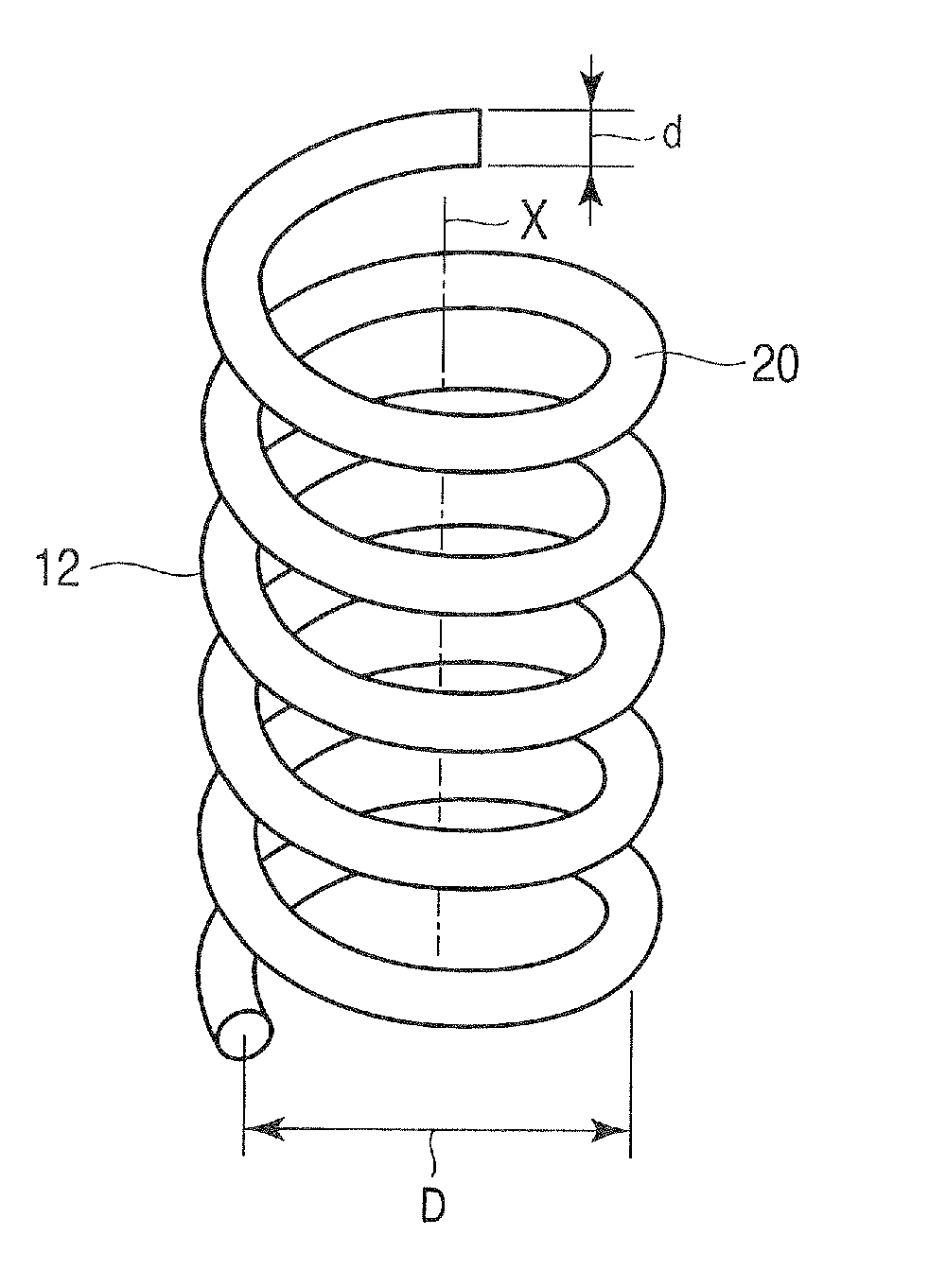
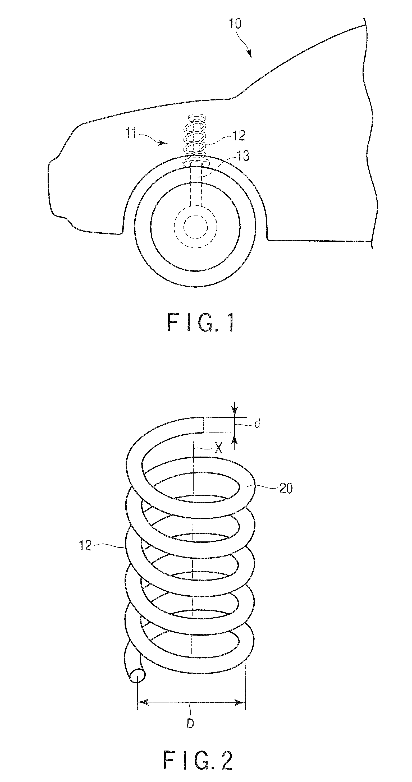
[0023]Steel that forms the spring wire 20 is highly corrosion-resistant spring steel (referred to as spring steel S for convenience in this description). The spring steel S is a type of steel enhanced in corrosion resistance, and its chemical composition (mass %) is 0.41 carbon, 1.73 silicon, 0.17 manganese, 0.53 nickel, 1.05 chromium, 0.163 vanadium, 0.056 titanium, 0.21 copper, and iron for the remainder.

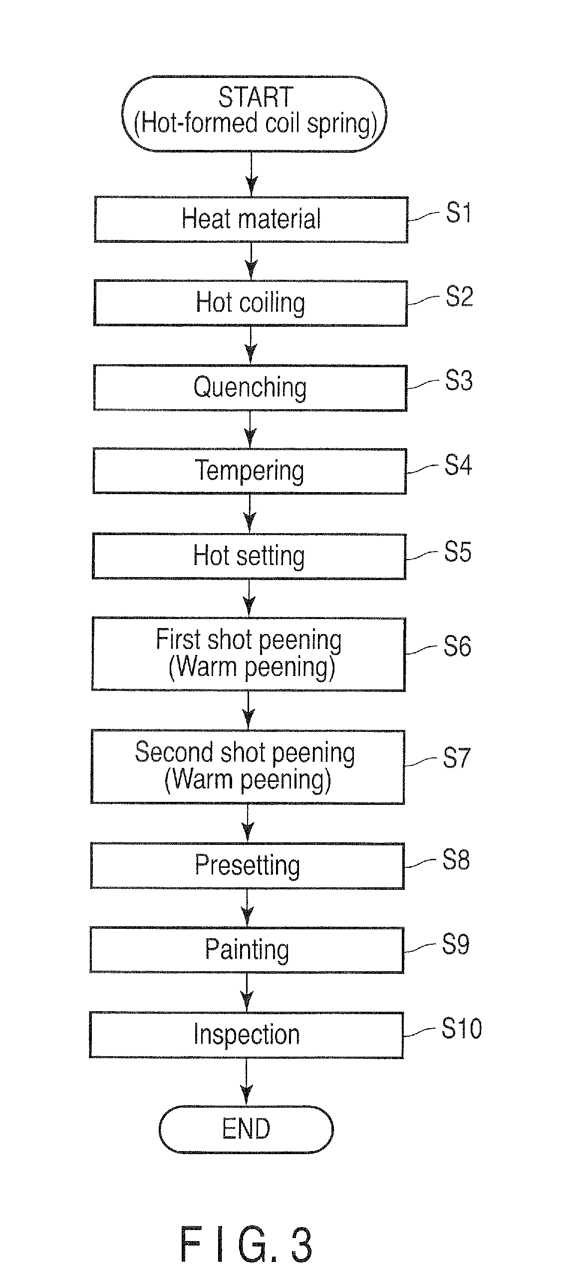
[0024]FIG. 3 shows manufacturing processes for a hot-formed coil spring. In a heating process S1, a spring wire for use as a material of the coil spring is heated to the austenitizing temperature (from A3 transformation point to 1,150° C.). The heated spring wire is bent into a spiral in a bending process (coiling process) S2. Thereafter, a heat treatment, including a quenching process S3, tempering process S4, etc., is performed.

[0025]The spring wire is thermally refined by the heat treatment so that its hardness ranges from 50 to 56 HRC. For example, a coil spring with a maximum...

example 2

[0044]The type of steel of a spring wire is SUP7 conforming to Japanese Industrial Standards (JIS). The chemical composition (mass %) of SUP7 is 0.56 to 0.64 carbon, 1.80 to 2.20 silicon, 0.70 to 1.00 manganese, 0.035 or less phosphorus, 0.035 or less sulfur, and iron for the remainder. Manufacturing processes of Example 2 are shared with Example 1 except for the shot peening conditions. The two-stage shot peening (warm double shot peening) based on a first shot peening process and second shot peening process is also performed in Example 2.

[0045]In the first shot peening process in Example 2, a first shot with a shot size of 0.87 mm was caused to impinge on the spring wire at a first projectile speed of 76.7 m / sec (impeller speed of 2,300 rpm). The treatment temperature is 230° C. In the second shot peening process, thereafter, a second shot with a shot size of 0.67 mm was caused to impinge on the spring wire at a second projectile speed of 46 m / sec (impeller speed of 1,380 rpm). Th...


PUM

PropertyMeasurementUnit
treatment temperaturesaaaaaaaaaa
temperatureaaaaaaaaaa

Abstract

A spring wire is subjected to a first shot peening process and a second shot peening process. In the first shot peening process, a first shot is projected on the spring wire at a first projectile speed. High kinetic energy of the first shot produces compressive residual stress in a region ranging from the surface of the spring wire to a deep position. In the second spring wire process, a second shot is projected at a second projectile speed lower than the speed of the first shot. The kinetic energy of the second shot is lower than that of the first shot. The low kinetic energy of the second shot increases the compressive residual stress in a region near the surface of the spring wire.

Description

CROSS REFERENCE TO RELATED APPLICATIONS[0001]This application is Continuation Application of PCT Application No. PCT / JP2010 / 054689, filed Mar. 18, 2010 and based upon and claiming the benefit of priority from prior Japanese Patent Application No. 2009-144461, filed Jun. 17, 2009, the entire contents of all of which are incorporated herein by reference.BACKGROUND OF THE INVENTION[0002]1. Field of the Invention[0003]This invention relates to a manufacturing method for a coil spring used in, for example, a suspension mechanism of a vehicle, and more particularly, to shot peening conditions.[0004]2. Description of the Related Art[0005]It is conventionally known that the fatigue strength of a coil spring can be improved by applying compressive residual stress to the vicinity of the surface of the spring by shot peening. Multistage shot peening is disclosed in Jpn. Pat. Appln. KOKAI Publication No. 2000-345238 or Jpn. Pat. Appln. KOKAI Publication No. 2008-106365. In the multistage shot p...

Claims


Application Information

Patent Timeline
Patent Type & Authority Patents(United States)
IPC IPC(8): C21D7/06
CPCB21F35/00B21F99/00B24C1/10Y10T29/479
Inventor TANGE, AKIRAOKADA, HIDEKIUESUGI, MOTOIHISANO, YOSUKE
Owner NHK SPRING CO LTD
Why Eureka
Try Eureka