LED assembly for a signage illumination

a technology of led assembly and signage, which is applied in the direction of lighting and heating equipment, semiconductor devices for light sources, instruments, etc., can solve the problems of high cost of operation, high cost of maintenance/repair, and low manufacturing cost, and achieves high efficiency, effective and inexpensive

Inactive Publication Date: 2013-12-17
ZON LED
View PDF33 Cites 25 Cited by
  • Summary
  • Abstract
  • Description
  • Claims
  • Application Information

AI Technical Summary

Benefits of technology

[0009]A light emitting diode (LED) light source assembly for a sign in which a message thereon is made more apparent by illumination and wherein the assembly is external to the sign housing. The assembly includes a housing comprising a base and a generally transparent cover. At least one LED module is operatively associated with the housing. The LED module includes a planar LED array consolidated onto a single light emitting chip. The LED array is configured to produce a light emission beam. The LED module includes a heat dissipating fixture. A light spreading system is disposed between the base and the cover. In order to overcome the disadvantages and shortcomings of prior art systems, the light spreading system includes a traverse deflector supported over the LED array and at least partially within the light emission beam thereof. The traverse deflector effectively, inexpensively and durably functions to spread the intense, concentrated light output from a planar LED array to achieve broad and even illumination of a billboard sign. The subject invention can be implemented without resorting to expensive lensed housing covers and does not require any special adaptations to the heat management strategies. As a result, the present invention enables high efficiency light transfer from a planar LED array to a sign surface.

Problems solved by technology

Such traditional approaches were reasonably effective, but were relatively expensive to manufacture, expensive to maintain / repair, expensive to operate, and suffered relatively short life cycles between bulb replacements.
Notwithstanding, LED applications have not successfully extended into billboard signage illumination due, at least in part, to difficulty obtaining an even light dispersion across the viewing surface.
However, planar LED arrays have not heretofore been successfully applied to billboard signage illumination applications.
Fundamental differences between the emission of light from a planar LED array as compared with an incandescent light source have rendered the traditional light dispersion techniques—chiefly reflectors placed behind the bulb and / or a lensed cover—to be found generally ineffective for planar LED array light source technologies.
The intense, unidirectional light emission beam from an LED light source, and in particular from a planar LED array configuration, results in a viewing angle so narrow that for billboard applications the traditional cover optics, Fresnel lensing, are not sufficiently effective to achieve the necessary light spread.
Furthermore, cover optics, e.g., those crafted with Fresnel lensing, are expensive when compared with a non-lensed cover.
Replacement of lensed covers due to damage and extended exposure to the elements contributes significantly to the high cost of traditional lighting solutions.
Another obstacle to use of planar LED array technology in billboard signage applications has been the issue of heat management.
It is well-known that LED light sources will fail prematurely without effective strategies for heat dissipation.
Thus, despite the recognized advantages of adapting outdoor signage lighting to LED's, there remains serious obstacles to successfully implementing LED concepts in this field due to fundamental differences in the respective light emission characteristics.

Method used


Image

  • LED assembly for a signage illumination
  • LED assembly for a signage illumination
  • LED assembly for a signage illumination

Examples


Embodiment Construction

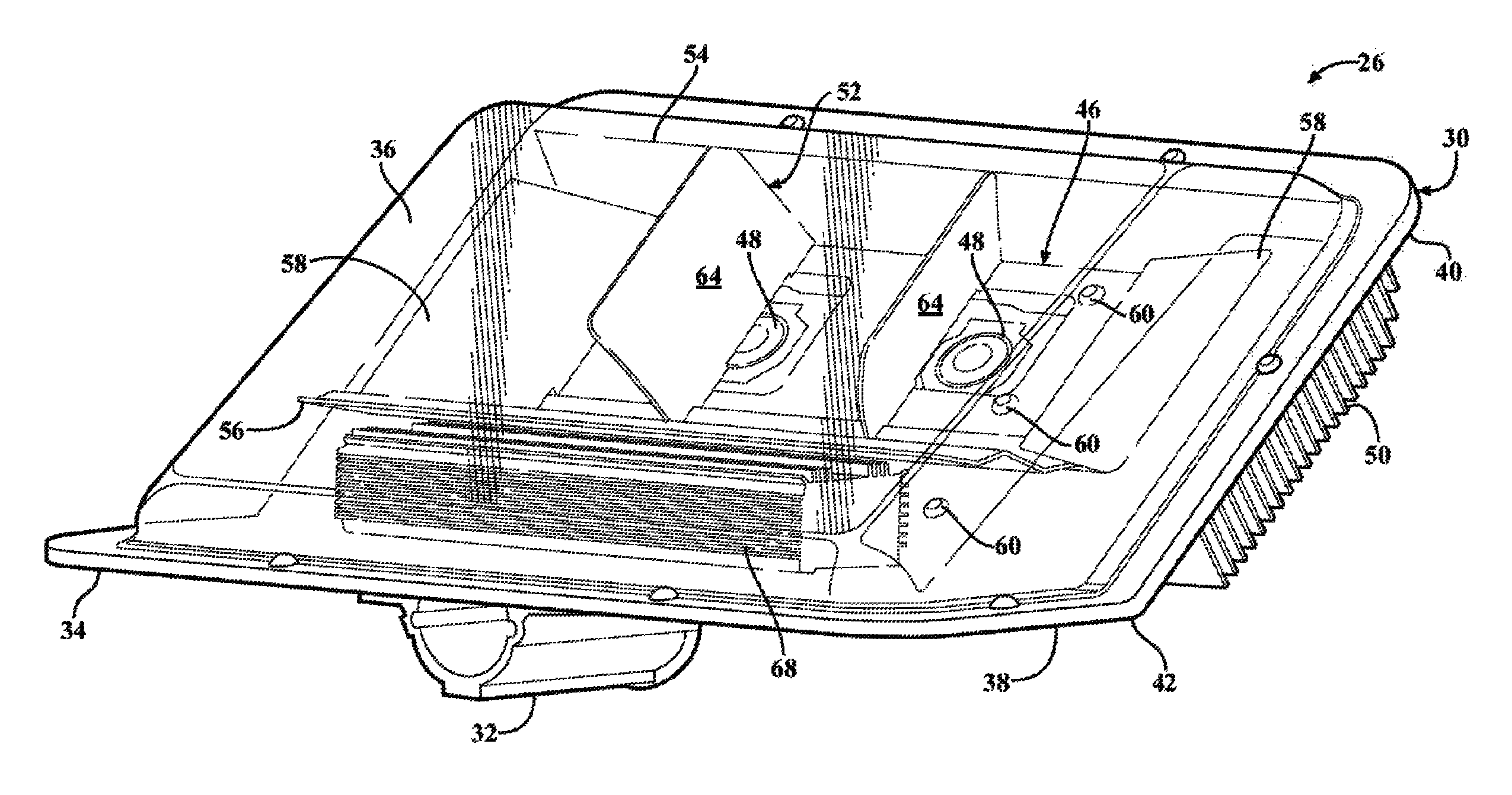
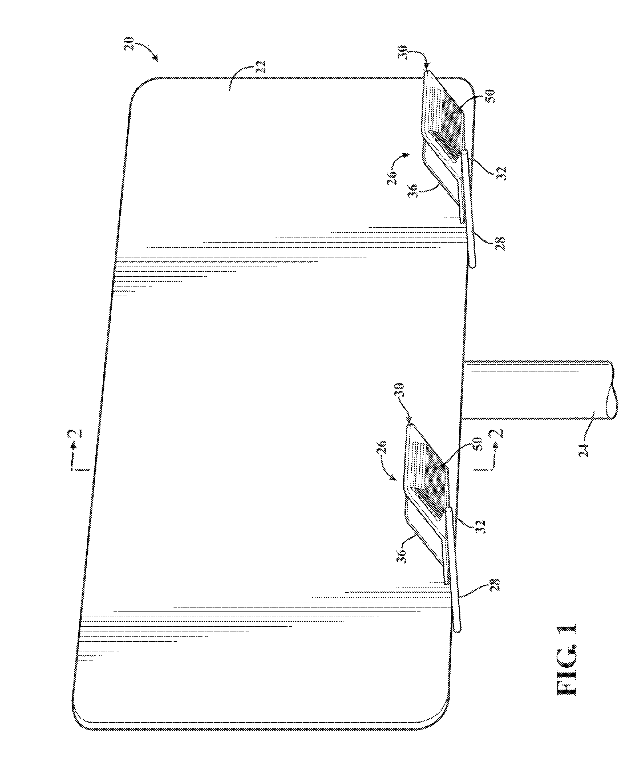
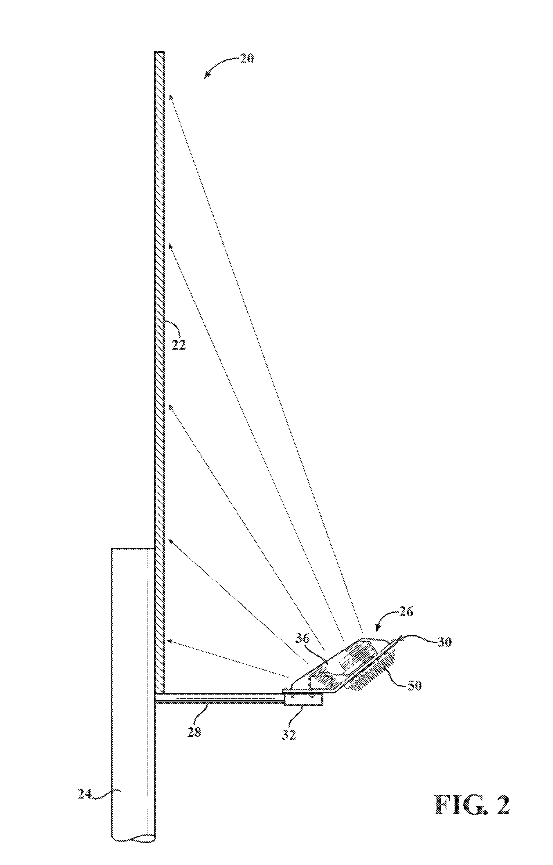
[0024]Referring to the figures wherein like numerals indicate like or corresponding parts throughout the several views, a billboard sign is generally shown at 20. The billboard sign 20 is of the type including a large, vertically oriented viewing surface 22 having a generally rectangular configuration. Although not depicted in FIG. 1, the viewing surface 22 is characteristically adorned with messages or other indicia intended to communicate a message of some sort to transient viewers. The billboard sign 20 may be elevated by a support post 24 which is shown as a single, centrally located column. However, in other configurations the support post 24 may comprise two or more stanchions or a supporting framework. In some applications, the billboard sign 20 may omit a support post 24 and be affixed in at elevated position such as to the side of a building.

[0025]A light emitting diode (LED) light source assembly is generally shown at 26. In the example of FIG. 1, two such LED light source...


PUM


Abstract

An LED light source assembly for signage illumination includes one or more planar LED arrays located with respect to a light spreading system for uniformly distributing light onto a viewing surface. The light spreading system includes a plurality of reflectors in combination with a transverse deflector disposed directly above and in the light emanating path of a planar LED array. The transverse deflector is oriented angularly and projects at least a portion of light onto a lateral reflector of the light spreading system. In one embodiment, a heat dissipation fixture is supported external to a housing assembly for improved heat management. The LED arrays and the plurality of reflectors and transverse deflectors are affixed directly to the heat dissipation fixture.

Description

CROSS REFERENCE TO RELATED APPLICATIONS[0001]This application is a Continuation-In-Part of U.S. patent application No. Ser. No. 12 / 790,745 filed May 28, 2010, the entire disclosure of which is hereby incorporated by reference and relied upon.BACKGROUND OF THE INVENTION[0002]1. Field of the Invention[0003]A light emitting diode (LED) light source assembly for a billboard type sign, and more particularly an improved light spreading system therefor.[0004]2. Related Art[0005]A billboard is a type of signage in the form of a large outdoor advertising structure typically found along busy roadways and other high traffic areas. Billboards often show slogans, visuals and other indicia that are painted or otherwise applied to a large, usually rectangular, vertical surface. Billboard advertisements are designed to visually catch the attention of people passing by and quickly create a memorable impression. To be effective, a billboard sign must present indicia that are visually discernible from...

Claims


Application Information

Patent Timeline
Patent Type & Authority Patents(United States)
IPC IPC(8): H01J7/24H01J61/52H01J17/28H01J19/74H01J13/32
CPCF21V29/004F21V29/763F21V29/74F21V29/75G09F13/02F21V23/0442F21V29/02F21Y2101/02G09F2013/222F21Y2115/10
Inventor STOLL, ARNOLDVON ZITTWITZ, PAUL
Owner ZON LED
Why Eureka
Try Eureka