Supercharge Your Innovation With Domain-Expert AI Agents!

Optical fiber lasers and amplifiers and methods for providing optical gain

a technology of optical fiber and amplifier, applied in the direction of cladded optical fibre, instruments, optical elements, etc., can solve the problems of increasing noise affecting the operation of optical fiber, etc., and achieve the effect of increasing the area

Active Publication Date: 2013-12-17
NUFERN
View PDF18 Cites 2 Cited by
  • Summary
  • Abstract
  • Description
  • Claims
  • Application Information

AI Technical Summary

Benefits of technology

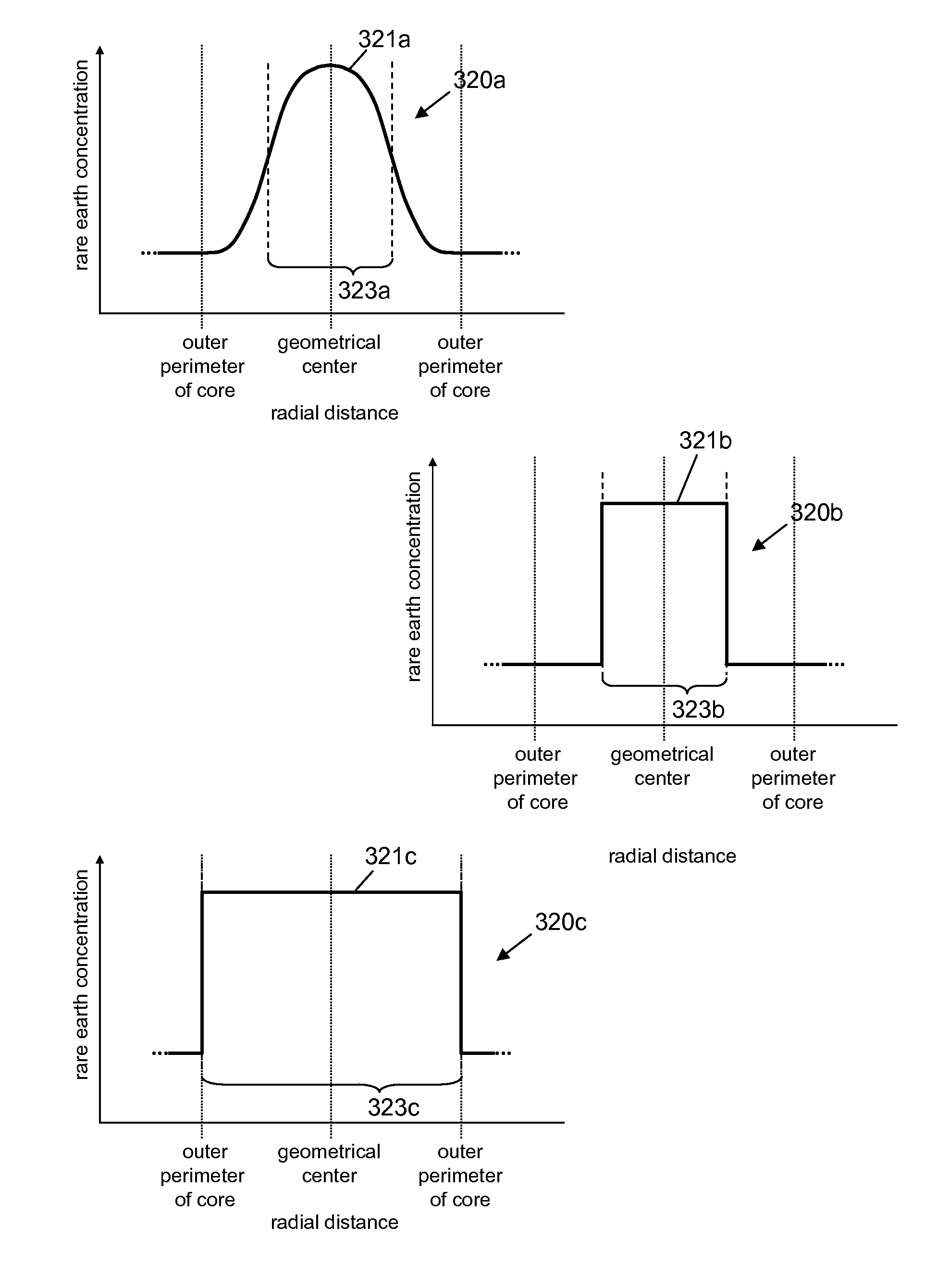
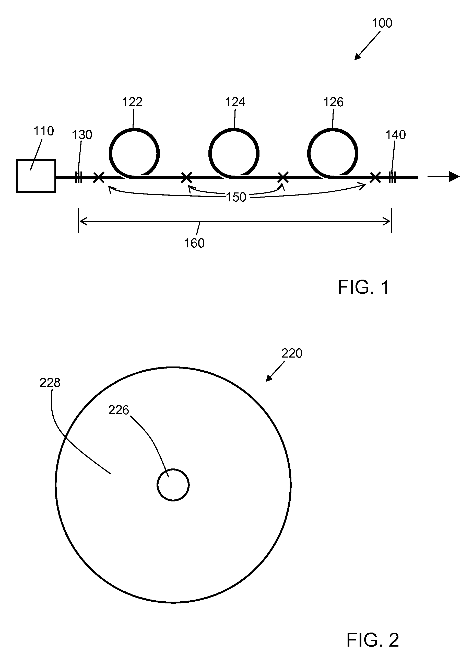
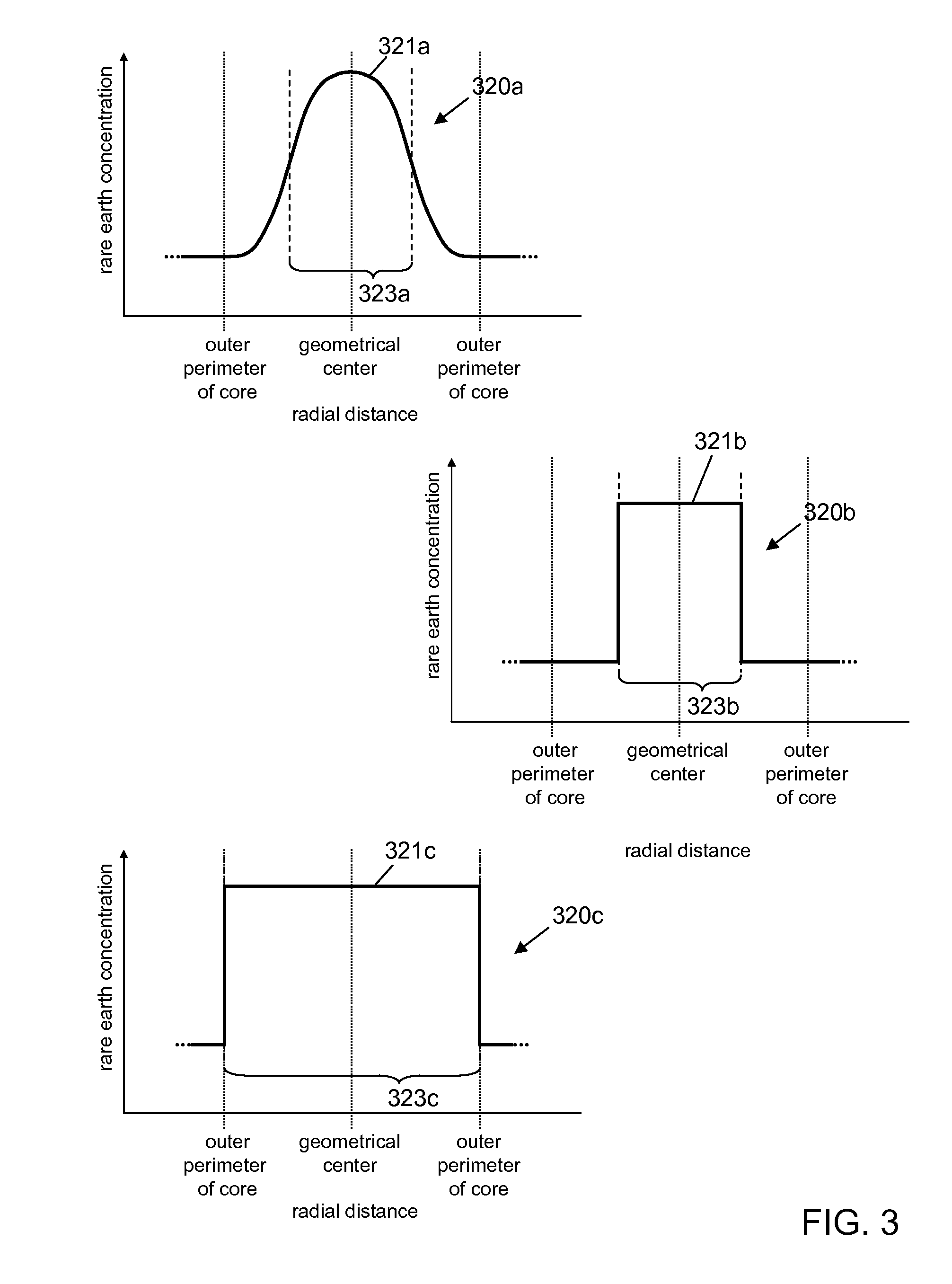
The patent describes an optical fiber device that provides optical gain at a selected wavelength. The device includes a source of optical pump energy, which is optically coupled to the optical fiber. The fiber has a core and a cladding that guide light of the selected wavelength. The core contains a rare earth material that provides the optical gain when exposed to the pump energy. The device can have three lengths of optical fiber, with different cross-sectional regions that have different concentrations of the rare earth material. The intensity of the pump energy is higher in one length of fiber than in the other two lengths, and the cross-sectional area of the core is larger in the region where the concentration is highest. The device can provide optical gain at a selected wavelength with high efficiency.

Problems solved by technology

In such optical fiber lasers and amplifiers, the pump radiation can be introduced directly to the core, which can be difficult due to the small size of the core, or can be introduced to the cladding layer surrounding the core and absorbed by the core as the rays propagating in the cladding layer intersect the core.
One complication is that cooperative effects that can cause excess loss, increase noise, or even damage the optical fiber.
Accordingly, in certain applications, it can be desirable to minimize up-conversion and luminescence in rare earth doped fiber devices, as they can tend to limit the gain achievable by the device, decrease pumping efficiency, and increase noise to unacceptable levels.

Method used


Image

  • Optical fiber lasers and amplifiers and methods for providing optical gain
  • Optical fiber lasers and amplifiers and methods for providing optical gain
  • Optical fiber lasers and amplifiers and methods for providing optical gain

Examples


example

[0091]To determine inversion for a single-fiber Yb-doped fiber amplifier, amplifier performance was simulated. The Yb-doped fiber amplifier had the following parameters:

[0092]Signal power: 1 W

[0093]Signal wavelength: 1064 nm

[0094]Pump power: 50 W

[0095]Pump wavelength: 976 nm

[0096]Core diameter: 20 μm

[0097]Core NA: 0.06

[0098]Cladding diameter: 400 μm

[0099]For the seed signal, a mode field diameter (MFD) of 17.5 μm was computed. The modeled intensity profile of the Gaussian beam is shown in FIG. 9. The intensity is given by the formula

[0100]I=a·ⅇ-8⁢x2MFD2

in which x is the radial position from the center of the core, and a is defined by the formula

[0101]a=8⁢P0π⁢⁢MFD2

in which P0 is the signal power.

[0102]By solving the applicable rate equations, the inversion distribution with respect to the radial position from the core center and along the length of the fiber were determined. The simplified rate equations for the 1064 nm transition in Yb are:

[0103]n⁢⁢2=R12+W12R12+R21+W12+W21+A21,⁢wher...


PUM


Abstract

The present invention relates generally to devices for the generation and amplification of electromagnetic energy. The present invention relates more particularly to optical fiber devices, such as lasers and amplifiers, useful for generating and amplifying optical energy. Accordingly, one aspect of the present invention is an optical fiber device for providing optical gain at a selected wavelength, the optical fiber device comprising: one or more sources of optical pump energy; a first length of optical fiber having a core comprising a first cross-sectional region within which the concentration of a rare earth does not fall below 50% of its highest concentration; and a second length of optical fiber comprising a core comprising a first cross-sectional region within which the concentration of the rare earth does not fall below 50% of its highest concentration, wherein the intensity of optical pump energy is higher in the first length of optical fiber than in the second, and the first cross-sectional region of the core of the second length of optical fiber is larger in area than the first cross-sectional region of the core of the first length of optical fiber.

Description

CROSS-REFERENCE TO RELATED APPLICATIONS[0001]The present application claims priority to U.S. Provisional Patent Application Ser. No. 61 / 245,308, filed on Sep. 24, 2009, which is hereby incorporated herein by reference in its entirety.BACKGROUND OF THE INVENTION[0002]1. Field of the Invention[0003]The present invention relates generally to devices for the generation and amplification of electromagnetic energy. The present invention relates more particularly to optical fiber devices, such as lasers and amplifiers, useful for generating and amplifying optical energy.[0004]2. Technical Background[0005]Optical fiber lasers and amplifiers are known in the art. In such lasers and amplifiers, rare earth materials disposed in the core of the optical fiber therein absorb pump radiation of a predetermined wavelength, and, in response thereto, provide or amplify light of a different wavelength for propagation in the core. For example, the well-known erbium doped fiber amplifier receives pump ra...

Claims


Application Information

Patent Timeline
Patent Type & Authority Patents(United States)
IPC IPC(8): H01S3/00
CPCH01S3/0675H01S3/08059H01S3/094003H01S3/06716H01S3/06729H01S3/094007H01S3/094061
Inventor FRITH, GAVIN P.
Owner NUFERN
Features
  • R&D
  • Intellectual Property
  • Life Sciences
  • Materials
  • Tech Scout
  • Unparalleled Data Quality
  • Higher Quality Content
  • 60% Fewer Hallucinations
Learn More