Pressure booster with double-seat valve

a technology of pressure booster and double seat valve, which is applied in the direction of multi-way valves, valve arrangements, mechanical equipment, etc., can solve the problems of rattling, excessive cost of manufacture of slide gate valves, and excessive cost of honing of cylinder bores, so as to prevent rattling, save costs, and buy cheap

Active Publication Date: 2013-12-24
SCANWILL FLUID POWER APS
View PDF14 Cites 10 Cited by
  • Summary
  • Abstract
  • Description
  • Claims
  • Application Information

AI Technical Summary

Benefits of technology

[0014]Once seat valves designed according to the invention are being used, the cylinder bore need not be honed anymore but may be realized with considerably higher tolerances and surface roughnesses. Because the cylinder bore as such does not contribute to the sealing effect anymore, its sole task is now to guide the control piston unit. A simple transition fit and, at the same time, requirements that are not very high, are sufficient for this purpose.
[0029]Ideally, at least one of the seat valves is designed such that a hysteresis results during the cycle of movement of the control piston unit between its two extreme positions. This takes place because the surface on the control piston unit to which the drivingly acting pressure is applied becomes smaller once the control piston unit bears on the valve seat concerned, while the other side of the control piston unit is exposed to the pressure of the control line on an undiminished surface area. This causes a kind of self-holding effect. If the pressure in the control line was sufficient to press the control piston unit onto its seat for a moment, then the control piston unit does not even open (inadvertently) when the pressure in the control line drops slightly. An additional result, possibly in conjunction with other force-limiting or attenuating measures, for example, is a slowed-down movement of the control piston unit during reversal. As soon as the pressure in the control piston unit drops, the control piston unit is not shot into its other position immediately and “with all force”, but first lifts off its seat and is then increasingly accelerated. It is thus possible to set a perfect timing, i.e. to begin the control process early or to ensure that it has an effect on the booster piston only when the booster piston has reached its desired dead center position (TDC / BDC); to be exact, when it comes to a free-piston engine, one cannot speak of dead centers, what is meant, therefore, are the points where the movement of the booster piston ideally reverses.

Problems solved by technology

Of course, this is a matter of milliseconds for each working cycle that can be gained or lost.
Fundamentally, the manufacture of a slide gate valve is exceptionally expensive.
Such a honing of the cylinder bore is exceptionally expensive.
Also, such an assembly is very susceptible to wear.
At the high frequencies intended here, small dirt particles having an abrasive effect already suffice to generate scores and the like in the control disk and / or the cylinder bore, thus reducing the quality of the sealing effect of the slide gate valve or disabling its sealing function to the point of unserviceability.
In addition, repair of such a slide gate valve is very complex.
The cylinder bore must be rehoned for the repairs (as a rule, the alternative, possible use of a new casing is uneconomical because in most cases, the slide gate valve is accommodated together with the booster piston in a joint casing).
Therefore, no series-produced slide gate valve can be inserted into the rehoned cylinder bore anymore.
This requires elaborate storage and the costly manufacture of special components.
A feed at higher pressures, such as 350 bar, 500 bar or more, poses problems in this pressure booster due to the leakage flows which then occur to a very considerable extent at the control disk, unless a very expensive control disk with an extremely exact fit is used in a special case, which could possibly push the limit up slightly.
If only higher feeding pressures are available (e.g., during mobile use), they must be reduced prior to being fed into the pressure booster, which is uneconomical.

Method used


Image

  • Pressure booster with double-seat valve
  • Pressure booster with double-seat valve
  • Pressure booster with double-seat valve

Examples


Embodiment Construction

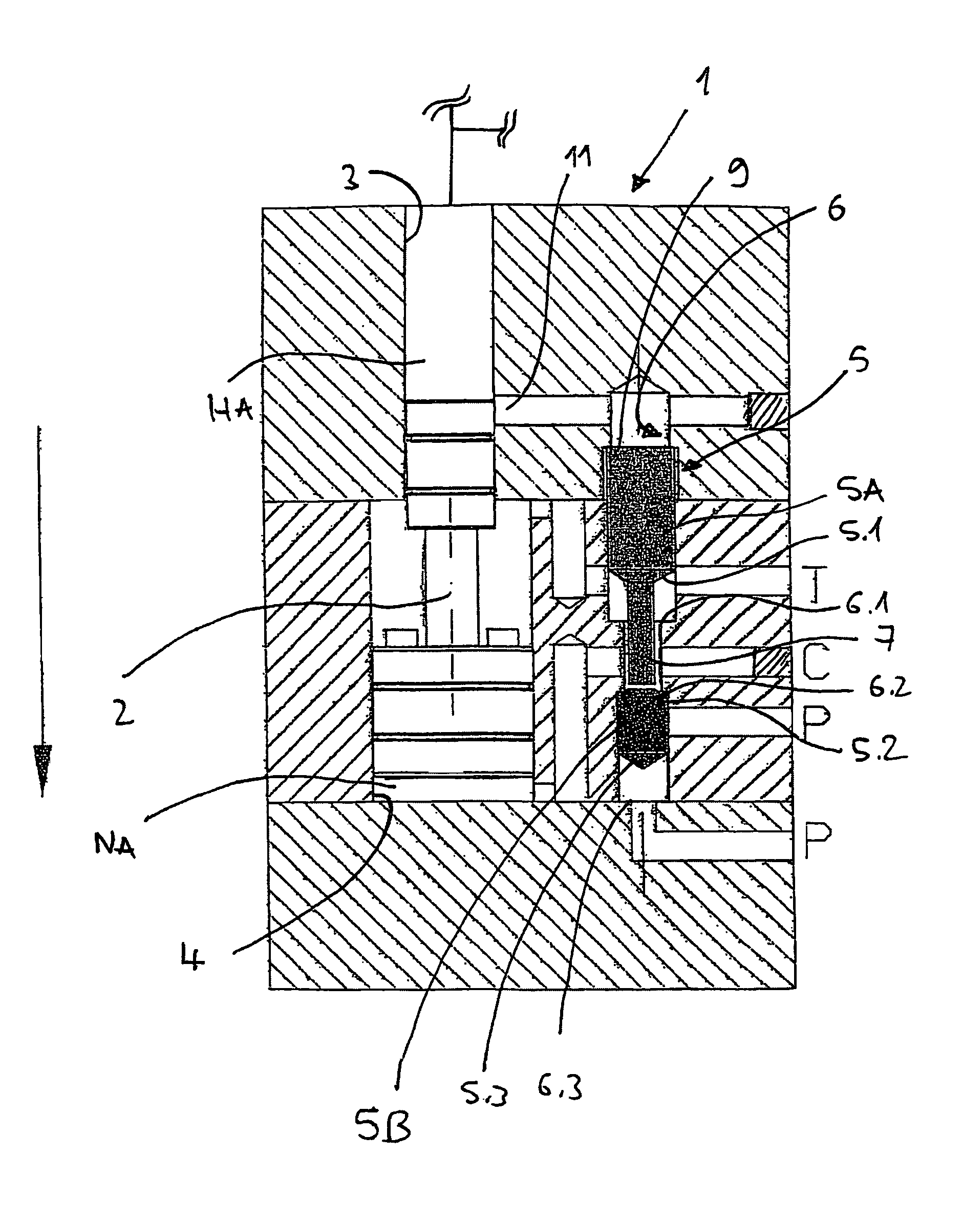
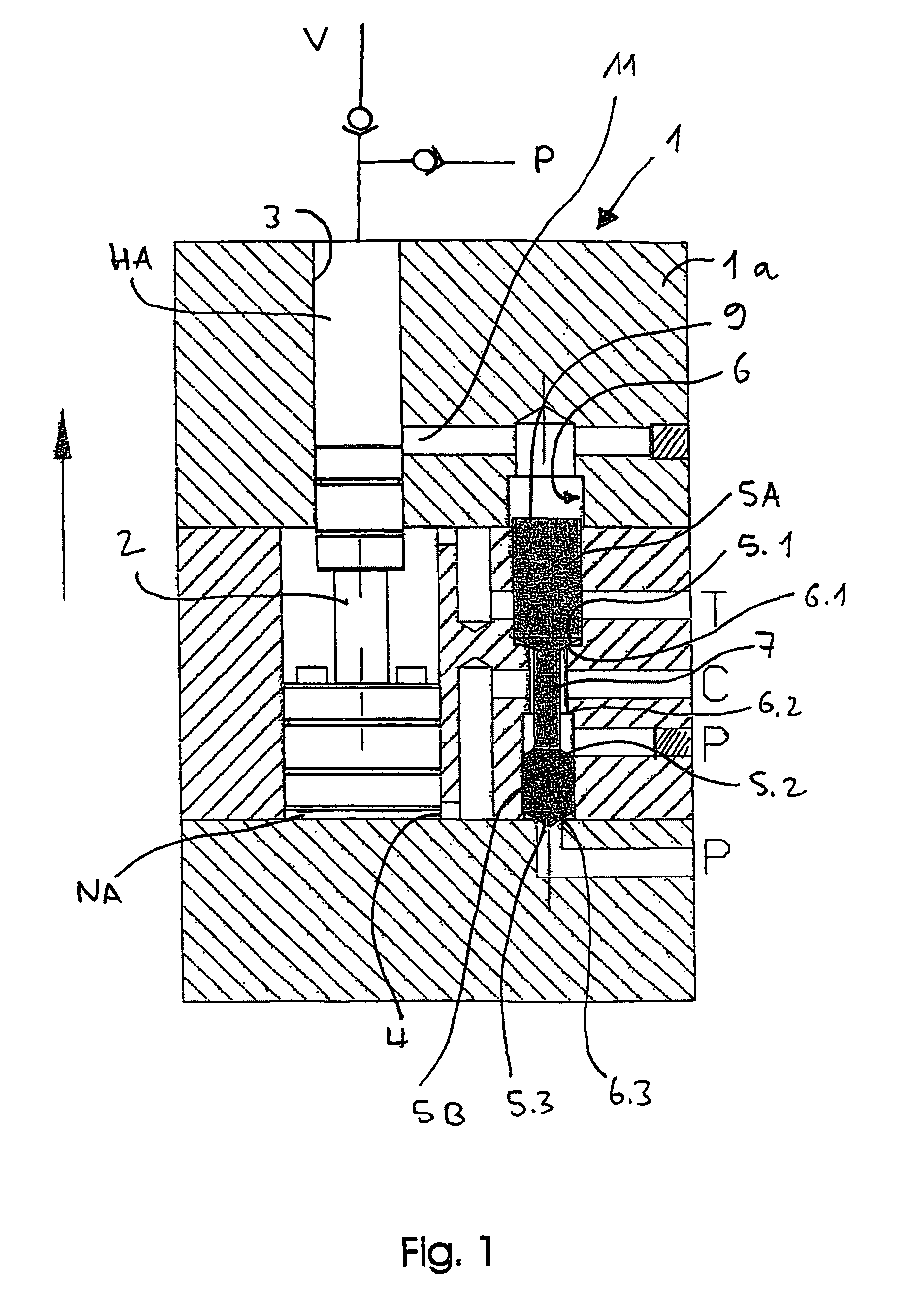
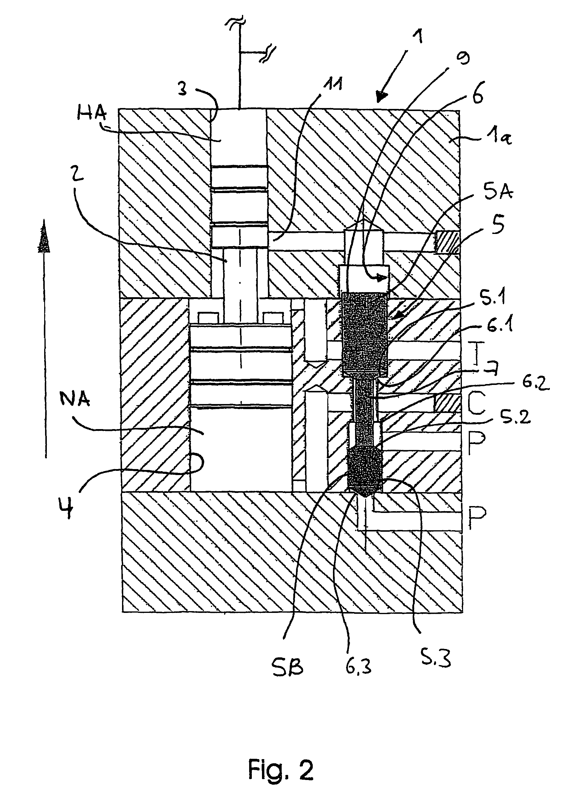
[0041]FIG. 1 shows an exemplary embodiment of the pressure booster according to the invention as it is preferably used for increasing pressure of hydraulic oil or water for supplying, for example, rescue cutters, clamping devices, high pressure fluid jet cutting tools and hydraulic blasting devices for concrete, rock and the like. The pressure booster is particularly suitable especially for the last purpose of use, because 2000 bar and more are often required on the high-pressure side, which can be realized most easily if a relatively high feeding pressure, which optionally is generated by a pressure booster (cascade system), can already be applied to the pressure booster arranged on the load side. Because where a higher boosting ratio must be realized on the side of the booster piston due to the limitation of the feeding pressure at the last stage, the discharged amount on the high-pressure side either becomes significantly smaller, or the pressure booster becomes significantly lar...


PUM


Abstract

The invention relates to a pressure boost for fluids, in particular hydraulic fluids, having a booster piston and a control piston unit, wherein a low-pressure side of the booster piston can be alternately connected by the control piston unit via a cylinder line to a low-pressure feed line and a discharge line, and a high-pressure side of the booster piston can be alternately connected to a high-pressure load line and a low-pressure feed line, wherein the control piston unit has two elements which are embodied as seat valves and which each interact with one valve seat and which are designed such that one of the elements intermittently seals off the low-pressure feed line, which can be connected to the low-pressure side of the booster piston, and the other element intermittently seals off the discharge line, which can be connected to the low-pressure side of the booster piston.

Description

FIELD OF THE INVENTION[0001]The invention relates to a pressure intensifier for fluids, in particular for hydraulic fluids.BACKGROUND OF THE INVENTION[0002]Such a pressure intensifier is known from European patent EP 0 825 348 B1 and from the associated German priority patent DE 196 33 258. In the assembly known from these patents, the working chamber on the low-pressure side of the booster piston is charged and discharged by means of a control piston reciprocated between two positions, a charging position in which it feeds the low-pressure working chamber with low-pressure fluid, and a corresponding discharge position.[0003]However, the known pressure intensifier employs a control piston designed as a one-piece valve actuator. The valve actuator has some special constructional features in order to meet the stated objective of this assembly. According to said patents, the tendency of the valve actuator to vibrate at high frequencies is to be reduced and resonance to be avoided, that...

Claims


Application Information

Patent Timeline
Patent Type & Authority Patents(United States)
IPC IPC(8): F04B17/00F04B35/00
CPCF04B9/1056F15B3/00F16K11/044
Inventor IVERSEN, JESPER WILL
Owner SCANWILL FLUID POWER APS
Why Eureka
Try Eureka