
Photoreflectance device

Active Publication Date: 2015-11-26
NEXCIS +1
View PDF3 Cites 3 Cited by
  • Summary
  • Abstract
  • Description
  • Claims
  • Application Information

AI Technical Summary

Benefits of technology

This patent aims to provide a photoreflectance device that can measure signals with high precision, even when the surface being probed is very rough. The device uses an integrating sphere to increase the light quantity and collect it from the probe beam, while also preventing unwanted light from interfering with the measurement. The device can make contactless measurements and is easy to move around the surface of the sample being probed.

Problems solved by technology

Indeed, the pump beam is only used to locally modify the dielectric properties of the material and it must not be detected in any case.
On the other hand, when the surface intended to be characterised is rough, a significant part of the probe beam is diffused rather than being reflected, and consequently, the intensity of the reflected probe beam is low.
The reflected signal detected is thus low and the signal-to-noise ratio is very poor.
Further, the pump beam is in turn diffused and consequently, part of the pump beam diffused is sensed by the detecting means, which interferes with the measurement of the reflected probe signal.

Method used


Image

  • Photoreflectance device
  • Photoreflectance device

Examples


Embodiment Construction

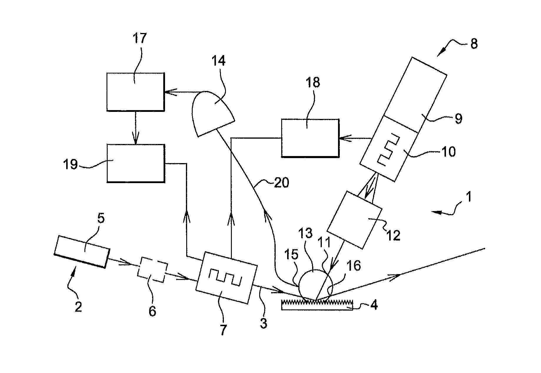
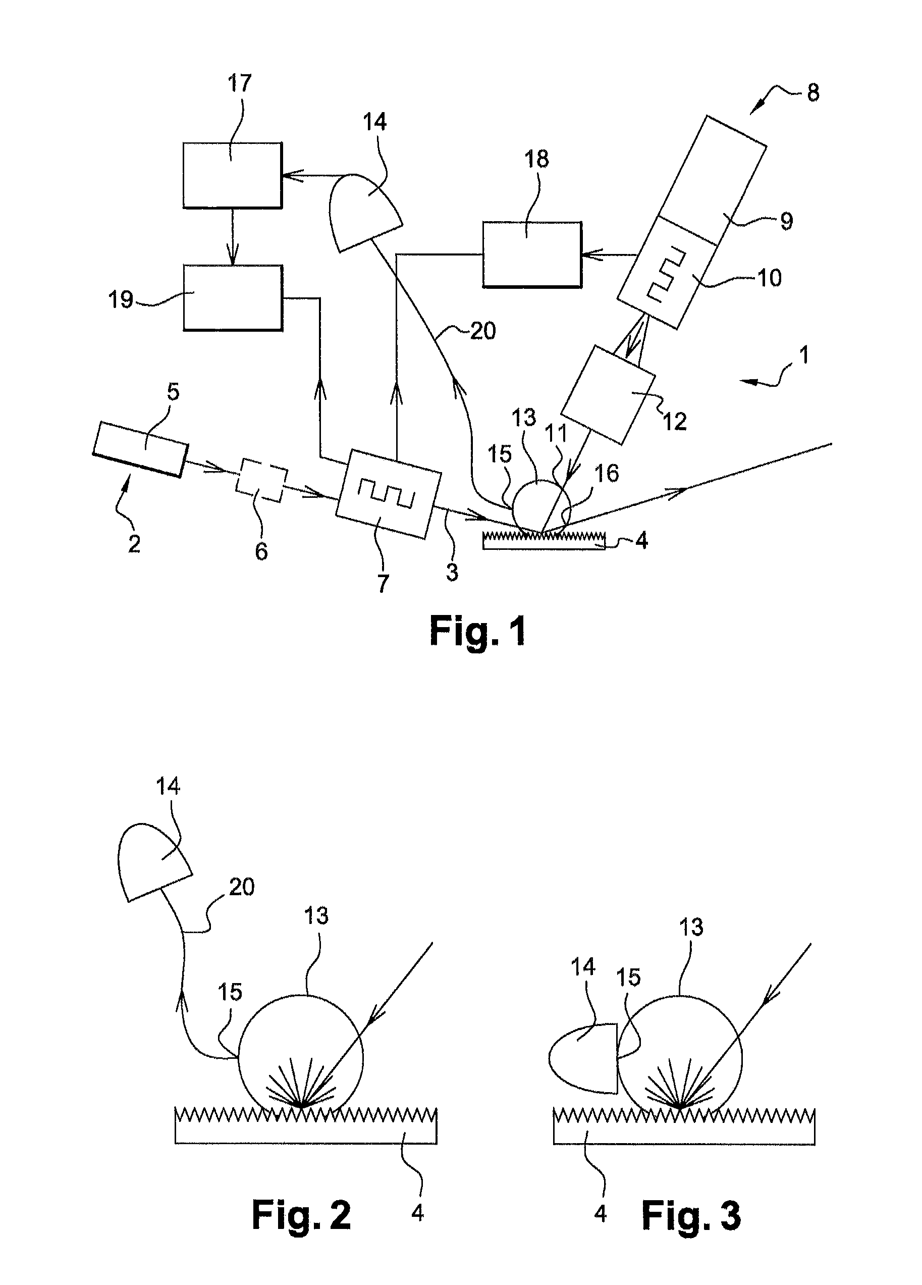
[0032]FIG. 1 represents a photoreflectance device according to one embodiment of the invention enabling the surface 4 of a sample to be characterised. This photoreflectance device 1 includes pump emitting means 2 capable of emitting a pump beam 3. This pump beam 3 is reflected by the sample. The pump emitting means 2 of the pump beam preferably include:[0033]a laser 5 emitting photons the energy of which can be adjusted as a function of the gap energy of the material to be characterised:[0034]a variable density neutral grey filter 6 enabling the pump light flux to be adjusted to the sample. Alternatively, instead of using this neutral variable density filter 6, the power can also be adjusted to the pump laser supply;[0035]second modulating means 7 capable of modulating the pump beam in frequency.

[0036]The photoreflectance device further includes probe emitting means 8 capable of emitting a probe beam 11. These probe emitting means 8 preferably include:[0037]a tunable polychromatic o...


PUM


Abstract

A photoreflectance device for characterizing a rough surface includes a pump beam emitter to emit a pump beam; a probe beam emitter to emit a probe beam; a detector to detect the probe beam reflected by the surface; an integrating sphere to collect the probe beam reflected by the surface, the integrating sphere including: a first output connected to the detector, and disposed so as to receive a majority of the probe beam reflected by the surface; a second output arranged so as to receive a majority of the pump beam reflected by the surface.

Description

TECHNICAL FIELD[0001]The present invention relates to a photoreflectance device for characterizing a rough or diffusing surface.STATE OF PRIOR ART[0002]Photoreflectance is a non-destructive process enabling a contactless probing in particular of semiconductor samples. Photoreflectance devices from prior art generally use a monochromatic probe beam to measure the light intensity reflected at the surface of a sample by means of a photodetector. A second beam, called a pump beam, which is a laser beam having a photon energy higher than the gap width of the sample, is also used to irradiate the surface of the sample so as to generate an electron / hole pair, which modifies the dielectric properties of the sample in the vicinity of its surface, and consequently the reflectivity of the sample for some wavelengths. The variation in light intensity from the probe beam reflected by the surface of the sample is measured, most often using synchronous detecting means. Thereby, a photoreflectance ...

Claims


Application Information

Patent Timeline
IPC IPC(8): G01B11/30
CPCG01B11/303G01N21/1717G01N2021/1725G01N2201/065
Inventor MOREAU, ANTONINBERMUDEZ, VERONICAESCOUBAS, LUDOVICSIMON, JEAN-JACQUES
Owner NEXCIS
Learn More