Hand-held blade sharpener

a technology of hand-held blades and sharpeners, which is applied in the field of harvesting, can solve the problems of time-consuming and high cost of assembly, and the cost of tabletop style sharpeners themselves is quite high, so as to reduce the risk of injury, reduce the handling, and save significant time

Active Publication Date: 2013-12-31
MILLS MARK S
View PDF15 Cites 8 Cited by
  • Summary
  • Abstract
  • Description
  • Claims
  • Application Information

AI Technical Summary

Benefits of technology

[0002]Currently, to sharpen blades on equipment used in textiles, lumber manufacturing, OSB board manufacturing and the farming industry, such as fiber processors, chippers, and forage harvesters of various sorts, the blades must be removed from the machine and sharpened in a tabletop-style sharpener. Such disassembly, reassembly obviously is time consuming driving up the cost. Further, the tabletop style sharpeners are themselves quite expensive. Lastly, reducing the handling of particularly the sharpened blades will also reduce the risk of injury to the blade mechanic.
[0003]The present invention provides a hand-held sharpener which can sharpen the blades in situ, such that the blades need not be removed, saving significant time, restoring the cutting machine to operating condition more quickly and economically. It is preferred that the hand-held sharpener of the present invention be utilized to back grind the blade so as not to reduce the feed angle on those machines, such as chippers, for example, which rely on the blades to feed the product through the machine.
[0004]The hand-held sharpener of the present invention features a) a rotary power tool including i) a handle having an opening extending there through; ii) a body having securement means for receiving attachments, the securement means defining a first longitudinal axis; b) a nose piece threadably attachable to the body through the opening in said handle, the nose piece having i) a first set of guide rollers affixed thereto at a first angle relative to the first longitudinal axis; ii) a second set of guide rollers mounted at a second different angle relative to the first longitudinal axis; whereby the first and second sets of guide rollers engage opposing faces of a blade to be sharpened. Preferably, the second set of guide rollers is secured to a second face plate, the second face plate being mounted to said nose piece in a manner to permit limited pivotal movement relative to the first longitudinal axis making the hand-held blade sharpener self-adjusting.

Problems solved by technology

Such disassembly, reassembly obviously is time consuming driving up the cost.
Further, the tabletop style sharpeners are themselves quite expensive.

Method used


Image

  • Hand-held blade sharpener
  • Hand-held blade sharpener
  • Hand-held blade sharpener

Examples


Embodiment Construction

)

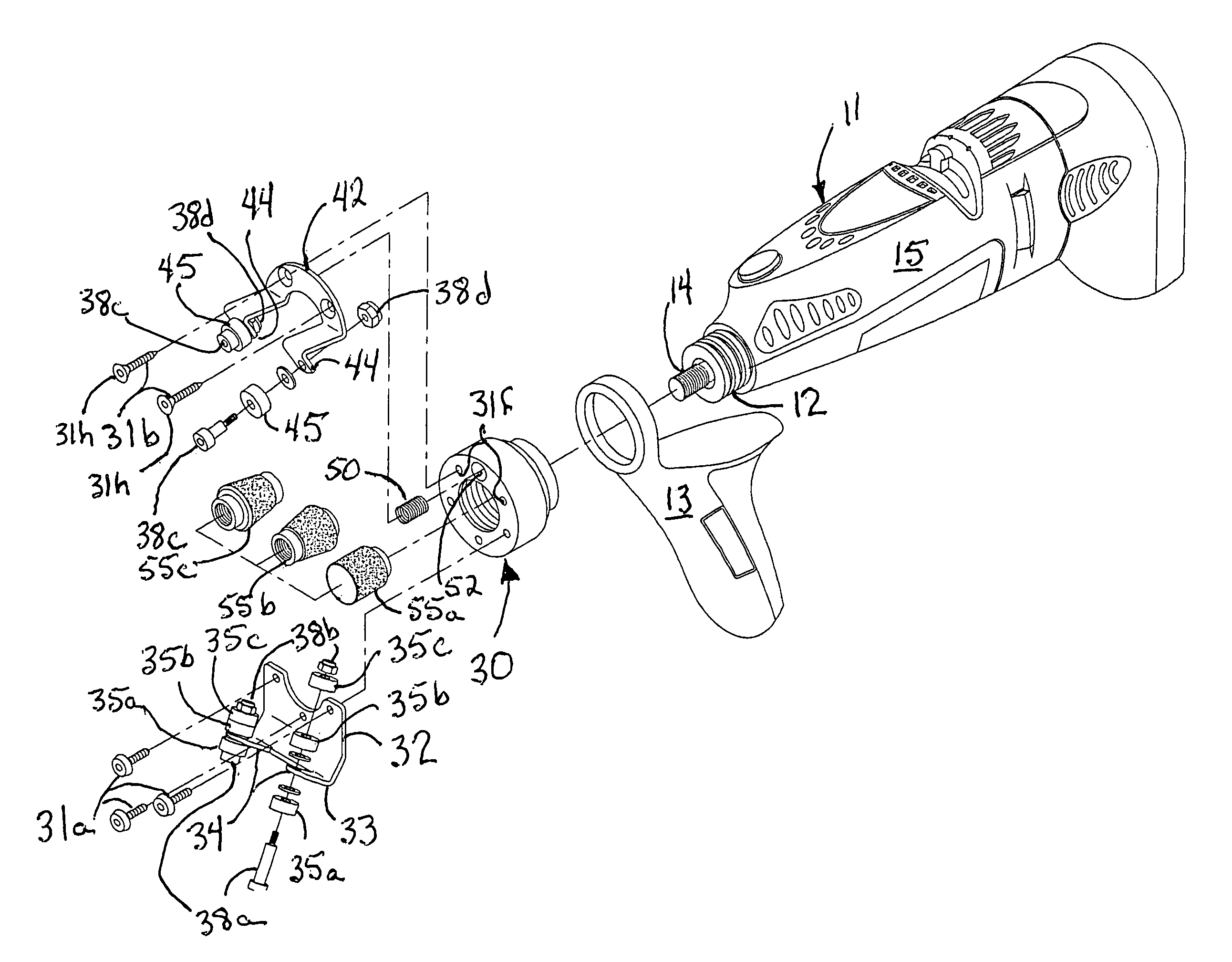
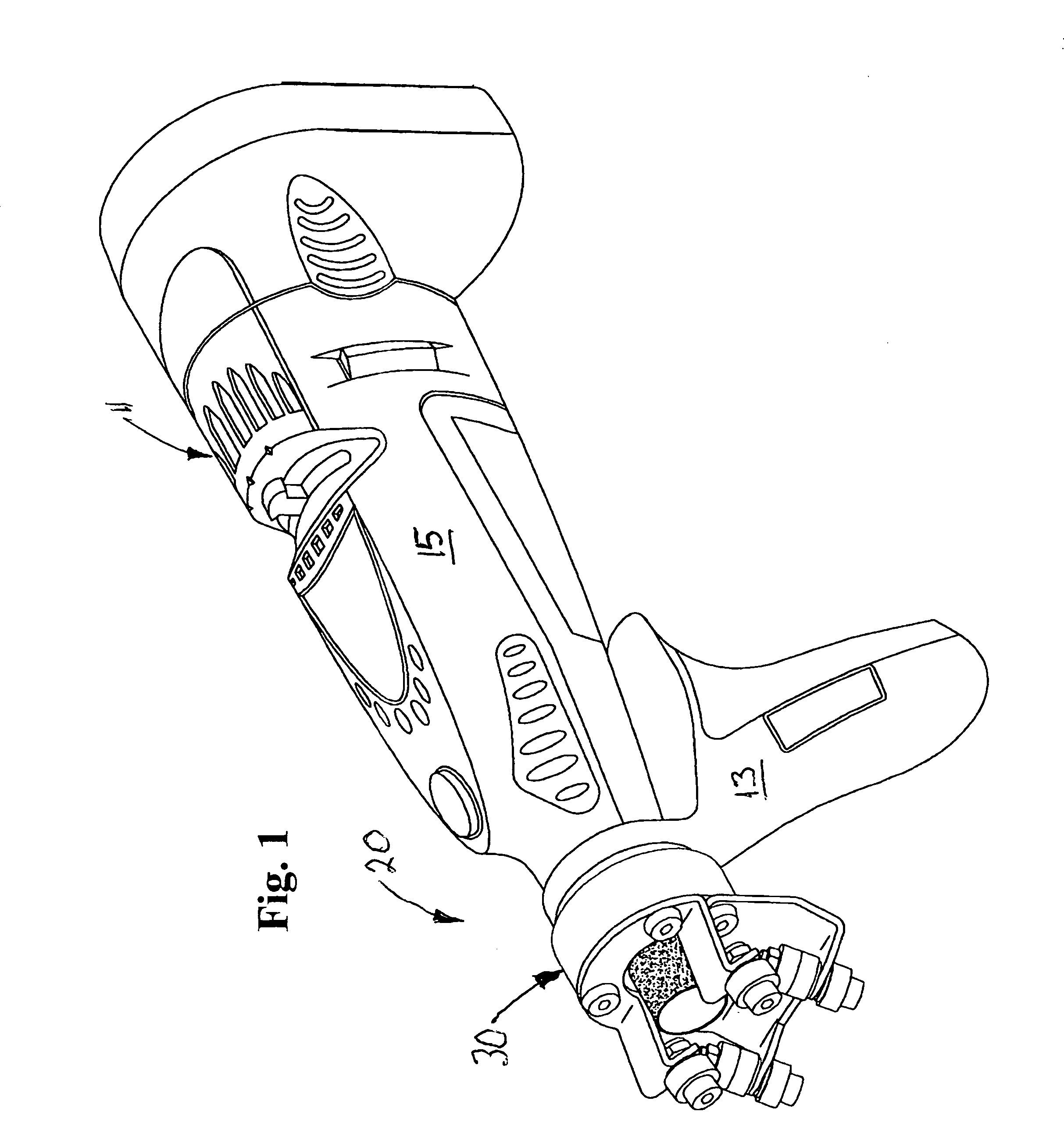
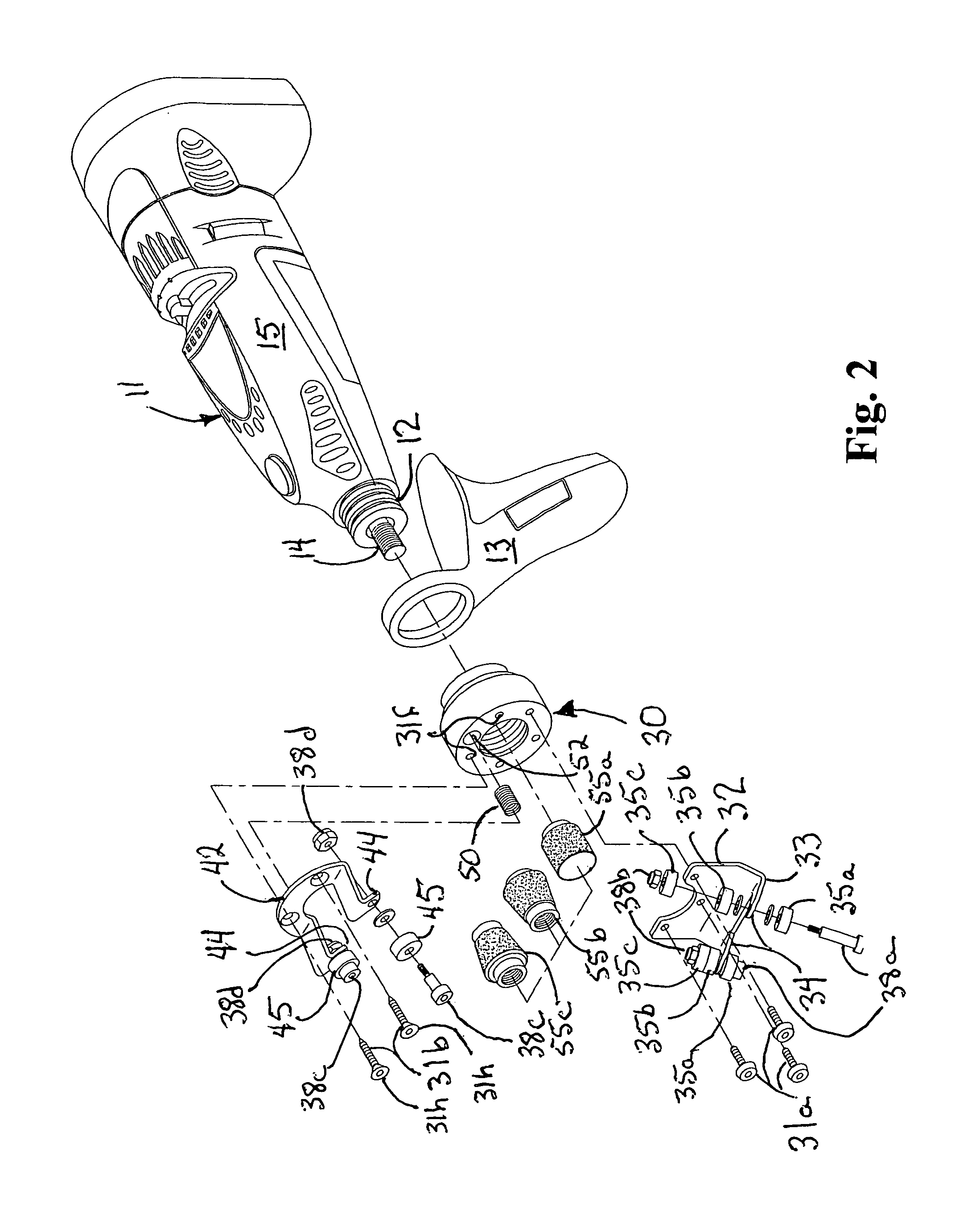
[0014]A first embodiment of the hand-held sharpener of the present invention is depicted in FIGS. 1-2 generally at 20. By way of example and not limitation, the rotary power tool 11 depicted in the drawing with which the features of the hand-held blade sharpener 20 of the present invention are implemented is a battery-powered Dremel 7700. Handle 13 is separate from the body 15 (FIG. 2) and, when nose piece 30 is threaded onto the front 12 of tool 11 through handle 13 capturing it there between, handle 13 can be rotated to any position through 360° relative to body 15 by loosening the attachment and rotating the handle or body, to facilitate sharpening of a blade 17 (FIG. 3).

[0015]Nose piece 30 has a first semi-circular face plate 32 mounted to a lower portion using screws 31a. First face plate 32 has a pair of arms 34 crooked at elbows 33, arms 34 mounting a first set of guide rollers, each of the arms 34 mounting a plurality (three shown) of guide rollers 35a, 35b, 35c which engag...


PUM

PropertyMeasurementUnit
angleaaaaaaaaaa
abrasiveaaaaaaaaaa
feed angleaaaaaaaaaa

Abstract

A battery-powered, hand-held blade sharpener features a self-adjusting set of guide rollers which widen to accommodate the thickness of the blade being sharpened. First and second semi-circular face plates mount sets of guide rollers, one of the face plates is mounted for pivotal movement and sprig-biased to a “closed jaw” position which the thickness of the blade opens as necessary.

Description

BACKGROUND AND SUMMARY OF THE INVENTION[0001]The present invention is directed to the field of harvesting. More particularly, the present invention is directed to a hand-held blade sharpener which permits in situ sharpening of blades on wood chippers, forage harvesters, and the like.[0002]Currently, to sharpen blades on equipment used in textiles, lumber manufacturing, OSB board manufacturing and the farming industry, such as fiber processors, chippers, and forage harvesters of various sorts, the blades must be removed from the machine and sharpened in a tabletop-style sharpener. Such disassembly, reassembly obviously is time consuming driving up the cost. Further, the tabletop style sharpeners are themselves quite expensive. Lastly, reducing the handling of particularly the sharpened blades will also reduce the risk of injury to the blade mechanic.[0003]The present invention provides a hand-held sharpener which can sharpen the blades in situ, such that the blades need not be remove...

Claims


Application Information

Patent Timeline
Patent Type & Authority Patents(United States)
IPC IPC(8): B24B9/00
CPCB24B3/36B24B23/02
Inventor MILLS, MARK, S.
Owner MILLS MARK S
Why Eureka
Try Eureka