Drive state control apparatus for vehicle

a control apparatus and driving state technology, applied in the direction of process and machine control, brake systems, instruments, etc., can solve the problems of reducing and maintaining the clutch drive current at a large value for a relatively long time, so as to reduce the maximum transmittable torque and reduce the wasteful consumption of clutch drive current.

Inactive Publication Date: 2013-12-31
AISIN AI CO LTD +1
View PDF11 Cites 9 Cited by
  • Summary
  • Abstract
  • Description
  • Claims
  • Application Information

AI Technical Summary

Benefits of technology

[0011]The present invention has been accomplished in order to solve the above-described problems, and an object of the present invention is to provide an on-demand-type drive state control apparatus for a vehicle which suppresses wasteful consumption of clutch drive current, which wasteful consumption would otherwise occur when the drive state of the vehicle is switched from a “four-wheel drive state” to a “two-wheel drive state,” and which prevents occurrence of large slippage at wheels.
[0017]Bu virtue of the above-described configuration, in the “four-wheel drive state,” the maximum transmittable torque decreases every time the predetermined condition is satisfied (i.e., decreases gradually (stepwise in a plurality of steps). In other words, the clutch drive current decreases every time the predetermined condition is satisfied; that is, decreases gradually (stepwise in a plurality of steps). Accordingly, as compared with the above-described first conventional example, wasteful consumption of the clutch drive current can be restrained. In addition, the drive torque transmitted to the first left and right wheels (drive wheels in the two-wheel drive state) increases every time the predetermined condition is satisfied; that is, the drive torque transmitted to the first left and right wheels increases gradually (stepwise in a plurality of steps). Accordingly, as compared with the above-described second conventional example, the first left and right wheels hardly cause large slippage.
[0018]Next, specific examples of the “predetermined condition” will be described. For example, preferably, the predetermined condition is such that a state in which the first and second left and right wheels are determined to have no slippage continues while the vehicle travels over a predetermined distance. In the case where this state continues, even when the drive torque transmitted to the first left and right wheels is increased slightly by means of decreasing the maximum transmittable torque slightly, conceivably, large slippage is unlikely to occur at the first left and right wheels. Accordingly, by means of determining the predetermined condition in this manner, it becomes possible to gradually decrease the maximum transmittable torque while stably maintaining a state in which large slippage does not occur at the first left and right wheels.
[0020]In the case where any of these conditions is satisfied, a road surface on which the vehicle is traveling is considered to be a “road surface which is high in road surface friction coefficient.” That is, even when the drive torque transmitted to the first left and right wheels is increased slightly by means of decreasing the maximum transmittable torque slightly, conceivably, large slippage is unlikely to occur at the first left and right wheels. Accordingly, by means of determining the predetermined condition in one of these manners, it becomes possible to gradually decrease the maximum transmittable torque while stably maintaining a state in which large slippage does not occur at the first left and right wheels.
[0022]By virtue of this configuration, in the case where the vehicle is in an instable state, such as a state in which slippage occurs at least one of the wheels, the proportions of the drive torques transmitted to the four wheels are changed such that the proportions become uniform. Accordingly, the degree of the slippage is restrained, and the vehicle can be placed in a more stable state.

Problems solved by technology

In the case of the on-demand-type apparatus, when the vehicle drive state is set to the “four-wheel drive state,” subsequently, the vehicle drive state must be switched from the “four-wheel drive state” to the “two-wheel drive state.” In other words, the maximum transmittable torque must be decreased from the present value (>0) to “0” in the “four-wheel drive state.” In this regard, a problem arises in determining a pattern in accordance with which the maximum transmittable torque is reduced.
For example, in the case where the vehicle has already moved from a “road surface which is low in road surface friction coefficient” to a “road surface which is high in road surface friction coefficient,” large slippage is unlikely to occur at the left and right rear wheels (the first left and right wheels) even if the vehicle is in the “two-wheel drive state.” Even in such a situation, the clutch drive current is maintained at a large value for a relatively long time.
That is, the clutch drive current is consumed wastefully.
For example, in the case where a “road surface which is low in road surface friction coefficient” continues, large slippage is likely to occur at the left and right rear wheels (the first left and right wheels) if the vehicle is in the “two-wheel drive state.” Irrespective of such a situation, the vehicle drive state is immediately switched from the “four-wheel drive state” to the “two-wheel drive state.” As a result, the drive torque transmitted to the left and right rear wheels increases suddenly, and large slippage may occur at the left and right rear wheels.

Method used


Image

  • Drive state control apparatus for vehicle
  • Drive state control apparatus for vehicle
  • Drive state control apparatus for vehicle

Examples


Embodiment Construction

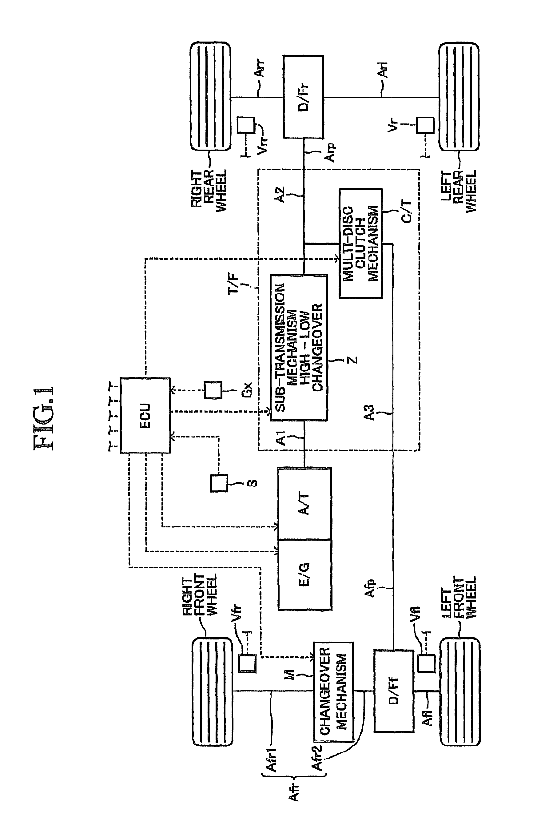
[0033]A vehicular drive state control apparatus according to an embodiment of the present invention (hereinafter also referred to as the “present apparatus”) will now be described with reference to the drawings. FIG. 1 shows the power transmission system of a drive system of a vehicle on which the present apparatus is mounted. This drive system includes a transfer T / F, a rear-wheel-side differential D / Fr, a front-wheel-side differential D / Ff, a changeover mechanism M, wheel speed sensors Vfr, Vfl, Vrr, Vrl, a longitudinal acceleration sensor Gx, a 2WD / 4WD changeover switch S, and an electronic control apparatus ECU.

[0034]The transfer T / F includes an input shaft A1, a first output shaft A2, and a second output shaft A3. The input shaft A1 is connected to an output shaft of an automatic transmission A / T connected to an engine E / G, and a power transmission system is formed between the input shaft A1 and the engine E / G. The first output shaft A2 is connected to the rear-wheel-side diffe...


PUM


Abstract

An on-demand-type drive state control apparatus for a vehicle is provided. In the case where acceleration slippage occurs at drive wheels (rear wheels) of a vehicle when a drive system is in a two-wheel drive state, the drive system is switched from the two-wheel drive state to a four-wheel drive state. That is, the maximum transmittable torque of a multi-disc clutch mechanism increases from “0” to a predetermined value. In the four-wheel drive state, the maximum transmittable torque decreases stepwise from the present value by a predetermined value every time the vehicle travels over a predetermined distance in a state in which none of the wheels cause acceleration slippages. That is, the clutch drive current supplied to the multi-disc clutch mechanism decreases gradually (stepwise or in a plurality of steps), and the drive torque distributed to the front wheels (rear wheels) decreases (increases) gradually.

Description

BACKGROUND OF THE INVENTION[0001]1. Field of the Invention[0002]The present invention relates to a drive state control apparatus for a vehicle which can perform changeover between a two-wheel drive state and a four-wheel drive state.[0003]2. Description of the Related Art[0004]Conventionally, there has been widely known a transfer which includes an input shaft, a first output shaft, and a second output shaft (sac, for example, Japanese Patent No. 3050255). The input shaft is connected to an output shaft of a transmission connected to an engine of a vehicle. The first output shaft is connected to left and right rear wheels (first left and right wheels), and the second output shaft is connected to left and right front wheels (second left and right wheels).[0005]This transfer includes a clutch mechanism which selectively establishes a “decoupled state” in which a power transmission system is formed only between the input shaft and the first output shaft, and a “coupled state” in which ...

Claims


Application Information

Patent Timeline
Patent Type & Authority Patents(United States)
IPC IPC(8): B60W10/02B60K6/54B60W10/10B60W20/00B60K17/354B60K6/44G06F17/00B60K6/52B60K6/36B60W10/12B60K17/348B60K17/344
CPCB60W2720/403B60K17/344B60K17/348B60W2550/12G06F17/00B60K23/0808B60W10/14B60K17/354B60W2520/263B60W2555/20
Inventor KOBAYASHI, KAZUTAKAAOYAMA, YOSHIYUKIMIYAZAKI, TAKESHIGEOHNO, AKIHIROSHIGETA, RYOHEIKATO, TOMOAKINAGAYAMA, GO
Owner AISIN AI CO LTD
Why Eureka
Try Eureka