Pressure exchanger

a technology of pressure exchanger and rotor, which is applied in the direction of hot gas positive displacement engine plants, piston pumps, pump components, etc., can solve the problems of reducing efficiency, reducing efficiency, and increasing the energy consumption of continuous flow operations, so as to achieve efficient transfer and improve efficiency. the effect of economy

a technology of pressure exchanger and rotor, which is applied in the direction of hot gas positive displacement engine plants, piston pumps, pump components, etc., can solve the problems of reducing efficiency, reducing efficiency, and increasing the energy consumption of continuous flow operations, so as to achieve efficient transfer and improve efficiency. the effect of economy

US8622714B2Active Publication Date: 2014-01-07FLOWSERVE HLDG

Image

  • Pressure exchanger
  • Pressure exchanger
  • Pressure exchanger

Examples


Embodiment Construction

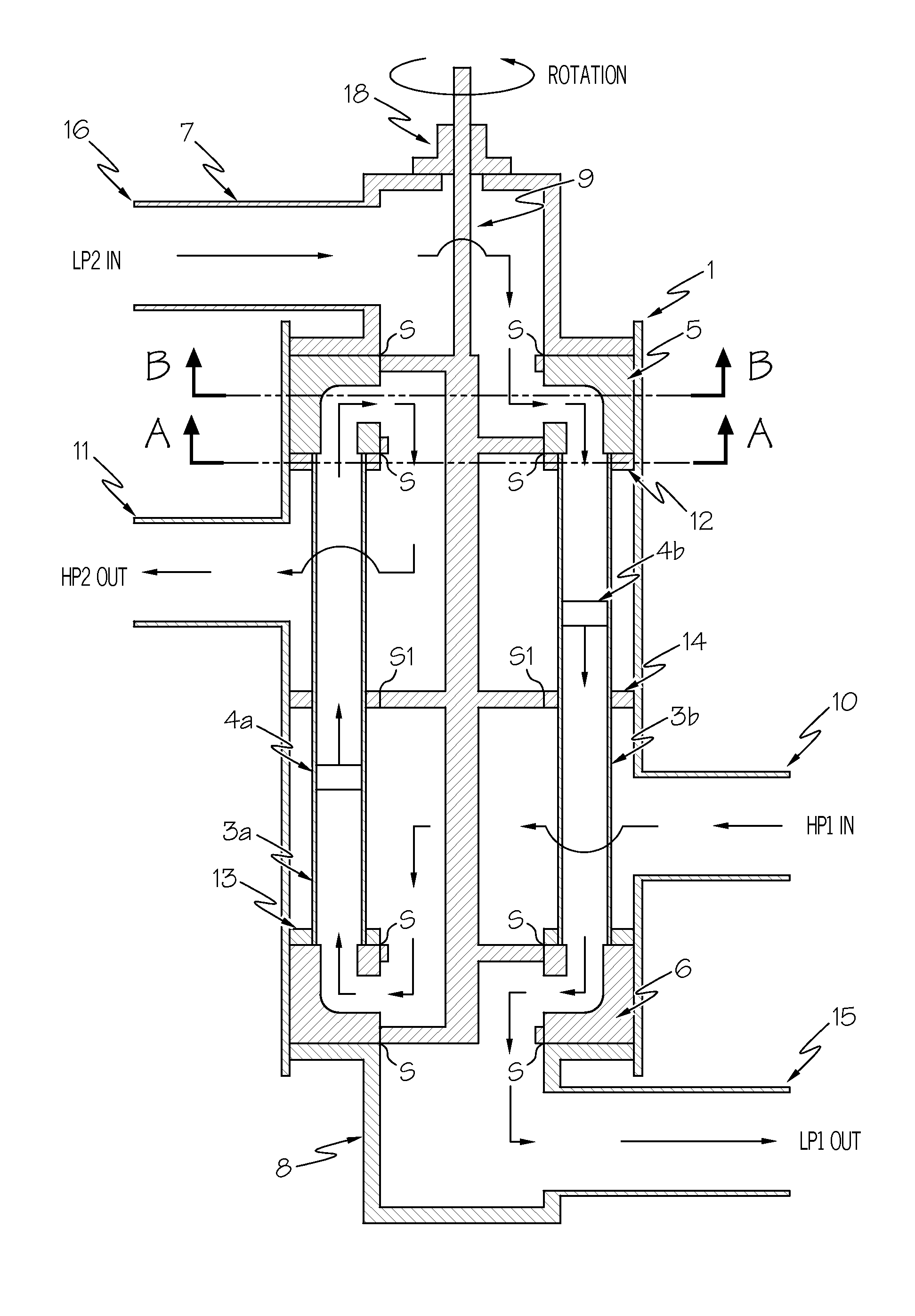
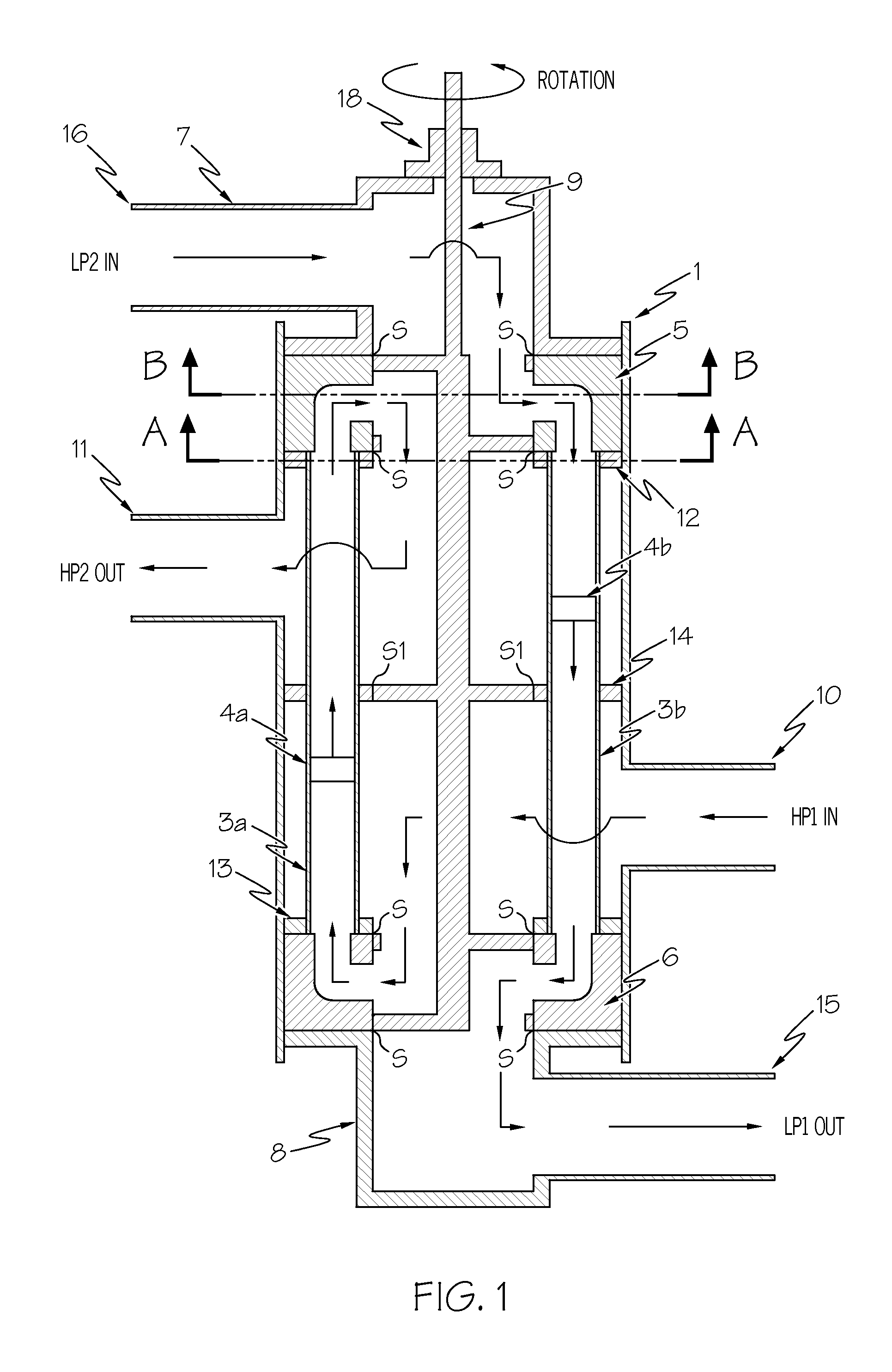
[0051]Referring first to FIG. 1, a simplified embodiment of the pressure exchange machine in accordance with the present invention is generally shown.

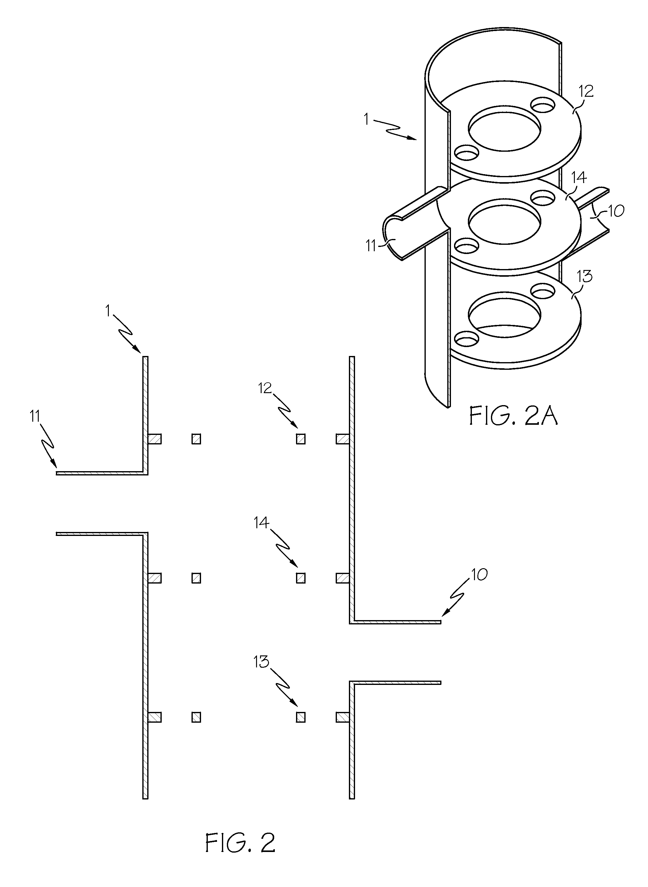
[0052]A pressure vessel 1 is provided with a first port 10 acting as a high pressure inlet of a first stream (“HP1 in”) and a second port 11 acting as a high pressure outlet (“HP2 out”). The pressure vessel 1, shown in more detail in FIGS. 2 and 2a, includes three septum plates 12-14 attached thereto. The septum plates 12 and 13 are located towards either end of the vessel 1, and the plate 14 is located towards its centre.

[0053]The three septum plates 12-14 of the pressure vessel 1 are bored out in substantially the same configuration as shown in FIG. 3, which shows the section A-A of FIG. 1. FIG. 3 also shows the two exchange ducts 3a and 3b, which are arranged around the outer ring of the septum plates.

[0054]Referring again to FIG. 1, duct pistons 4a and 4b are provided in the exchanger ducts 3a and 3b, respectively, to reduce mixing...


PUM


Abstract

A pressure vessel provided with a first port acting as a high pressure inlet of a first stream and a second port acting as a high pressure outlet. A rotatable valve element is located in the center of the machine. In operation, a fluid stream is introduced to the machine at high pressure where it then passes through the open ports of the valve element and into flow distributor causing upward displacement of a first duct piston, resulting in pressurization and flow of a second fluid. At the same time the second fluid is introduced to the machine at low pressure and flows into the pressure exchange duct, causing downward displacement of a second duct piston and resulting in flow of the first fluid below the duct piston, which then flows into the lower flow distributor, into the valve element, and then out of the pressure vessel.

Description

CROSS-REFERENCE TO RELATED APPLICATION[0001]This application is a continuation in part of application Ser. No. 12 / 092,970, filed Nov. 11, 2008 now U.S. Pat. No. 8,308,444 that was based on PCT Application PCT / GB2006 / 004236 filed Nov. 14, 2006.BACKGROUND OF THE INVENTION[0002]The present invention relates to a pressure exchanger machine. The preferred embodiments disclosed below utilize fixed exchange ducts and a rotary valve element.[0003]Such pressure exchangers are sometimes called ‘flow-work exchangers’ or ‘isobaric devices’ and are machines for exchanging pressure energy from a relatively high pressure flowing fluid system to a relatively low pressure flowing fluid system. The term fluid as used herein includes gases, liquids and pumpable mixtures of liquids and solids.[0004]In processes where a fluid is made to flow under pressure, only a relatively small amount of the total energy input is consumed in the pressurizing of the fluid, the bulk of the energy being consumed in main...

Claims


Application Information

Patent Timeline
07 Jan 2014
Publication
US8622714B2
IPC
F02C3/02
CPC
F04B7/0023
Inventors
ANDREWS, WILLIAM, T.