

DSL protection circuit
a protection circuit and circuit technology, applied in the field of circuit technology, can solve problems such as splitter damage, splitter protection, and affecting the density of the board
- Summary
- Abstract
- Description
- Claims
- Application Information
AI Technical Summary
Benefits of technology
Problems solved by technology
Method used
Image

Examples
embodiment 1
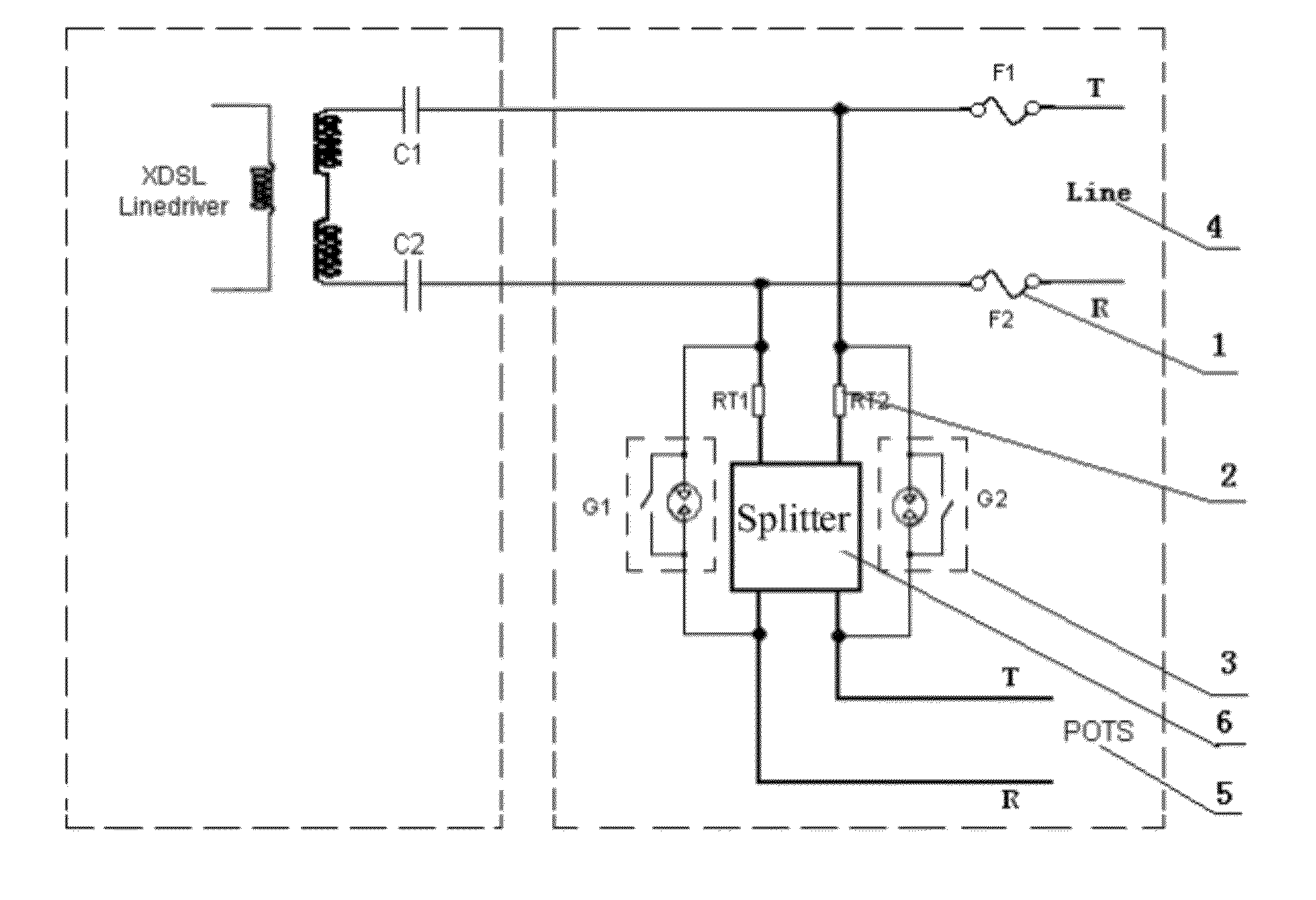
[0030]The embodiment of the present application provides a DSL protection circuit, as shown in FIG. 5. The DSL protection circuit includes: a DSL and POTS broadband and narrowband mixed signal port 4, a narrowband POTS port 5, and a splitter 6, where the DSL and POTS broadband and narrowband mixed signal port 4 is connected to the narrowband POTS port 5 through the splitter 6, and a line on which an input end or output end of the splitter is cascaded with a restorable current-limited component 2 for limiting abnormal current; the line on which the splitter 6 and the restorable current-limited component 2 are cascaded is connected in parallel with a voltage-limited component 3 for bypass of the splitter 6; a line on which the DSL and POTS broadband and narrowband mixed signal port 4 is or a line on which the narrowband POTS port 5 is cascaded with an overcurrent fuse component 1.
[0031]The restorable current-limited component 2 according to the embodiment of the present application is...
embodiment 2
[0035]Based on Embodiment 1, specifically, the DSL protection circuit provided in the embodiment of the present application includes: a DSL and POTS broadband and narrowband mixed signal port (line end 4: DSL and POTS mixed signal port), a narrowband POTS port (POTS end 5), and a splitter 6. The DSL and POTS broadband and narrowband mixed signal port is connected to the narrowband POTS port through the splitter 6. An input end of the splitter 6, that is, the end connected to the line end 4 is cascaded with thermistors RT1 and RT2, and a gas discharge tube G1 is connected in parallel with a line on which the splitter 6 is cascaded with the thermistor RT1, and a gas discharge tube G2 is connected in parallel with a line on which the splitter 6 is cascaded with the thermistor RT2; an end of the narrowband POTS port, that is, the end where the splitter is connected to the line end 4 is cascaded with fuses F1 and F2.
[0036]In this embodiment, G1 and G2 are two-electrode gas discharge tube...
embodiment 3
[0048]A DSL protection circuit provided in the embodiment application has a basically similar circuit structure as the circuit according to Embodiment 2. As shown in FIG. 10, the difference lies in that the thermistors RT1 and RT2 are cascaded on a side where the splitter is connected to the POTS end.
[0049]The protection principle of the DSL protection circuit provided in the embodiment application is similar to the protection principle of the circuit according to Embodiment 2, and details are not described herein again.
PUM
 Abstract
Description
Claims
Application Information