Exhaust-gas turbocharger

a turbocharger and exhaust gas technology, applied in the direction of machines/engines, stators, liquid fuel engines, etc., can solve the problems of neither the fin nor the outer housing are excessively melted during fusion, and achieve the effect of reducing stress peaks, compensating manufacturing tolerances, and improving service li

Active Publication Date: 2014-01-14
BENTELER AUTOMOBILTECHNIK GMBH
View PDF14 Cites 26 Cited by
  • Summary
  • Abstract
  • Description
  • Claims
  • Application Information

AI Technical Summary

Benefits of technology

[0008]The present invention resolves prior art problems by providing the bearing flange on the outside with a wrap-around fin via which the outer housing is welded with the bearing flange. The fin has a base portion which is wider in relation to its free end. Widening the base portion enables a transfer of the amount of heat introduced via the outer housing via a wider cross sectional area into the solid base body of the bearing flange. The fin is thus intended to merge into the base body of the bearing flange in a quasi smooth or also essentially rounded manner. The change in cross section of the fin is advantageously continuous or has only small jumps to substantially avoid high temperature gradients.
[0009]According to another advantageous feature of the present invention, the fin has a wall thickness in a range from 0.9 to 1.3 of a wall thickness of the outer housing. The range relates hereby to the portions of the fin and the outer housing which are joined to one another. As a result, the wall thickness of the fin can be best suited to the wall thickness of the outer housing such that a fusion-welded joint results in a substantially even heat introduction into the fin and into the outer housing. By adjusting the wall thicknesses to one another, neither the fin nor the outer housing are excessively melted during fusion-welding. As a result of the wall thickness adjustment of the fin and the outer housing, the weld impact zones are adjusted, a fact that also contributes to an optimum heat transfer and to less material impairment of the weld joint. Fatigue caused by heat can thus be reduced.
[0016]Basically, it is advantageous to connect the impeller housing with the bearing flange at a distance to the outer housing. As a result, the amount of heat, introduced by the outer housing and the impeller housing into the bearing flange, can be dispersed so as to eliminate the presence of undesired high temperature gradients in the attachment zone with the bearing flange. In particular, heat is not directly transferred from the inner system to the outer housing and from there into the bearing flange via the welding impact zone.
[0018]As a result of an exhaust-gas turbocharger according to the invention, the outer housing can be reliably positioned in a groove next to the fin. Manufacturing tolerances can be compensated. Realization of an even, high-quality joining process with little heat introduction is possible, which is feasible by the connection of wall thicknesses which are substantially the same, whereby the wall thicknesses should not deviate by more than 10-30%. The decrease in stress peaks improves service life. Finally, joining the outer housing in the outer region of the bearing flange is generally beneficial because residues, especially weld spatter, caused by the joining process, cannot migrate into the interior of the turbine housing.

Problems solved by technology

By adjusting the wall thicknesses to one another, neither the fin nor the outer housing are excessively melted during fusion-welding.

Method used


Image

  • Exhaust-gas turbocharger
  • Exhaust-gas turbocharger
  • Exhaust-gas turbocharger

Examples


Embodiment Construction

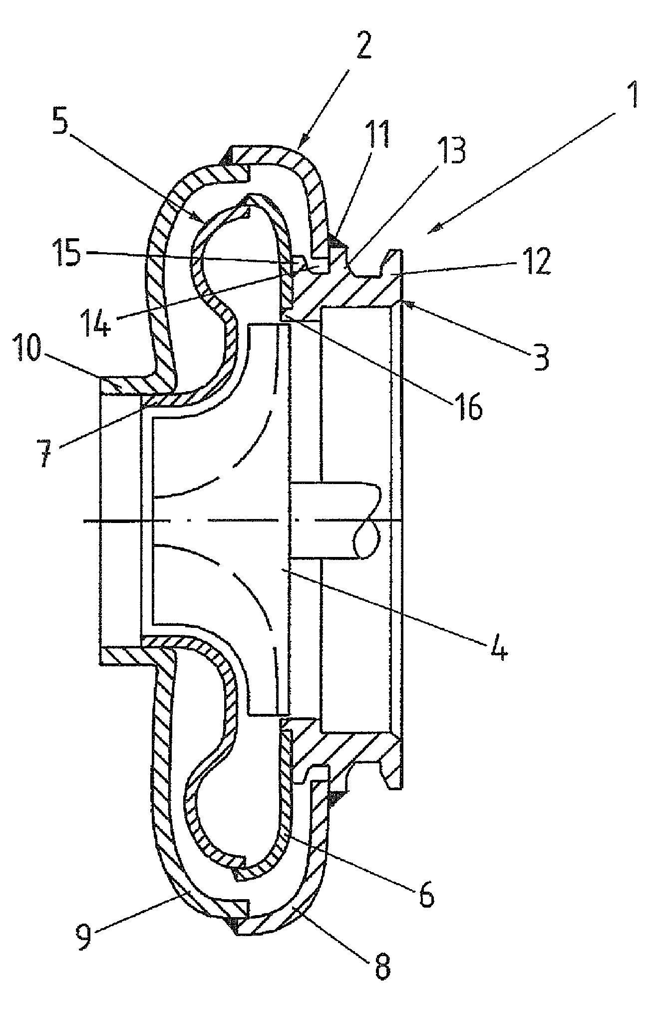
[0023]Throughout all the figures, same or corresponding elements may generally be indicated by same reference numerals. These depicted embodiments are to be understood as illustrative of the invention and not as limiting in any way. It should also be understood that the figures are not necessarily to scale and that the embodiments are sometimes illustrated by graphic symbols, phantom lines, diagrammatic representations and fragmentary views. In certain instances, details which are not necessary for an understanding of the present invention or which render other details difficult to perceive may have been omitted.

[0024]Turning now to the drawing, and in particular to FIG. 1, there is shown a cross section through a turbine housing, generally designated by reference numeral 1, of an exhaust-gas turbocharger in accordance with the present invention. The turbine housing 1 includes an outer housing 2 which is welded with a bearing flange 3. The bearing flange 3 is provided for securement...


PUM


Abstract

An exhaust-gas turbocharger includes a bearing flange for securement of the exhaust-gas turbocharger to a bearing housing of a turbine wheel. The bearing flange is provided with an outer circumferential fin having a base portion which terminates in a free end. The base portion is defined by a width which is greater than a width of the free end. An outer housing is welded to the outer circumferential fin of the bearing flange, and accommodates an impeller housing.

Description

CROSS-REFERENCES TO RELATED APPLICATIONS[0001]This application claims the priority of German Patent Application, Serial No. 10 2009 042 260.9-13, filed Sep. 22, 2009, pursuant to 35 U.S.C. 119(a)-(d), the content of which is incorporated herein by reference in its entirety as if fully set forth herein.BACKGROUND OF THE INVENTION[0002]The present invention relates to an exhaust-gas turbocharger.[0003]The following discussion of related art is provided to assist the reader in understanding the advantages of the invention, and is not to be construed as an admission that this related art is prior art to this invention.[0004]Internal combustion engines for motor vehicles are increasingly charged by turbochargers to reduce fuel consumption. Fuel consumption is, however, also influenced by the weight of the exhaust system so that turbochargers should be as lightweight as possible but still be robust enough to withstand significant mechanical and in particular thermal stress during operatio...

Claims


Application Information

Patent Timeline
Patent Type & Authority Patents(United States)
IPC IPC(8): F03B11/02
CPCF02B39/00F05D2220/40F01D25/243F02C7/12F05D2230/232
Inventor GRUSSMANN, ELMARSMATLOCH, CHRISTIANLANDERMANN, LARS
Owner BENTELER AUTOMOBILTECHNIK GMBH
Why Eureka
Try Eureka