Variable compliance wheel

a wheel and compliance technology, applied in the field of wheels with variable compliance, can solve the problems of inability of the system to maintain adequate tire pressure, sensitivity to elements, cost, etc., and achieve the effects of improving the lateral performance of the wheel, reducing waste and rework, and improving maneuvering performan

Active Publication Date: 2014-01-21
MILLENWORKS
View PDF10 Cites 13 Cited by
  • Summary
  • Abstract
  • Description
  • Claims
  • Application Information

AI Technical Summary

Benefits of technology

[0007]With the inner and outer wheel segment attachment points close together tensioning the spokes, the vertical stiffness of the wheel is increased. In the example of the vehicle wheel, this increased stiffness generally provides excellent on-road performance (cornering, steering feel, low rolling resistance, etc.) and increased payload carrying capacity and increased durability at high speeds.
[0008]With the inner and outer wheel segment attachment points spread apart from one another, the vertical stiffness of the wheel is reduced, enlarging the contact patch of the wheel with, for example, the ground, baggage, or other material. In the example of a printer, the stiffness of the print roller can be modulated to compensate for plate wear, extending the life of the plate and improving the throughput of the press. In the example of the vehicle wheel, the tire / terrain enveloping performance is improved, while the lower ground pressure gives the vehicle better off-road mobility on soft soils like mud, sand, and snow.
[0009]Continuing with the example of the vehicle, the inner and outer wheel segment attachment points spread far apart from one another which allows the vehicle to be lowered, thereby facilitating transportation in low clearance vehicles like aircraft. The lower ground pressure of this configuration is also beneficial to ramps and cargo floors that have strict limits on floor loading pressure due to floor structure limitations imposed by weight constraints, as is the case with many aircraft.
[0011]Multiple inner and outer wheel segments can be stacked to produce a wheel with varying radial stiffness across the width of the wheel. This is beneficial for improving the lateral performance of the wheel by controlling the wheel's dynamic camber. In the example of wheels supporting a conveyer belt, this varying stiffness across the wheel width may help direct or steer baggage in a desired direction. In the example of a printer, the varying radial stiffness of a printer roller may direct paper in a desired direction or area, such as continuously adjusting the registration of multicolor press runs. This reduces the waste and rework associated with misregistered press output.
[0012]In the example of the vehicle, the dynamic camber can adjusted during cornering to improve maneuvering performance. This can also be beneficial for changing the heading of the vehicle while driving with little or no steering of the tire. By making the stiffness of the innermost pair of inner and outer wheel segments stiffer than the outermost pair, resulting forces at the wheel / road contact patch will serve to pull the vehicle in the direction of the outermost pair of wheel segments. Further, by reversing the relative stiffness between the two sections, the wheel can force the vehicle in the opposite direction. This has the potential of simplifying the steering system, reducing cost and weight, improving the durability of the suspension / steering system by eliminating vulnerable steering links, and reclaiming the swept volume lost to the tire as it steers for other vehicle components or cargo. Additionally, the radial wheel stiffness, when modulated at a high rate, can be used to counteract vehicle pitch and heave vibrations, augmenting or even replacing the vibration isolation functions of the vehicle's suspension system.

Problems solved by technology

The shortcomings of this design are complexity, sensitivity to the elements, cost, and inability of the system to maintain adequate tire pressure when the tire is badly damaged.

Method used


Image

  • Variable compliance wheel
  • Variable compliance wheel
  • Variable compliance wheel

Examples


Embodiment Construction

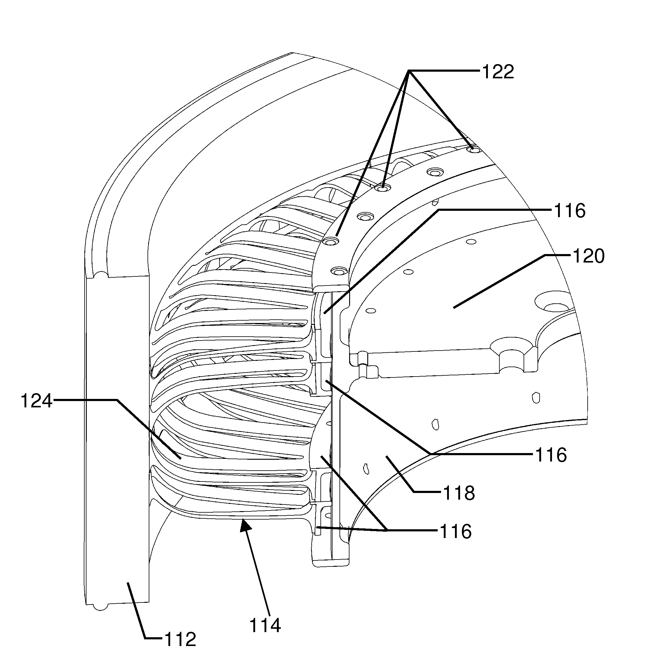
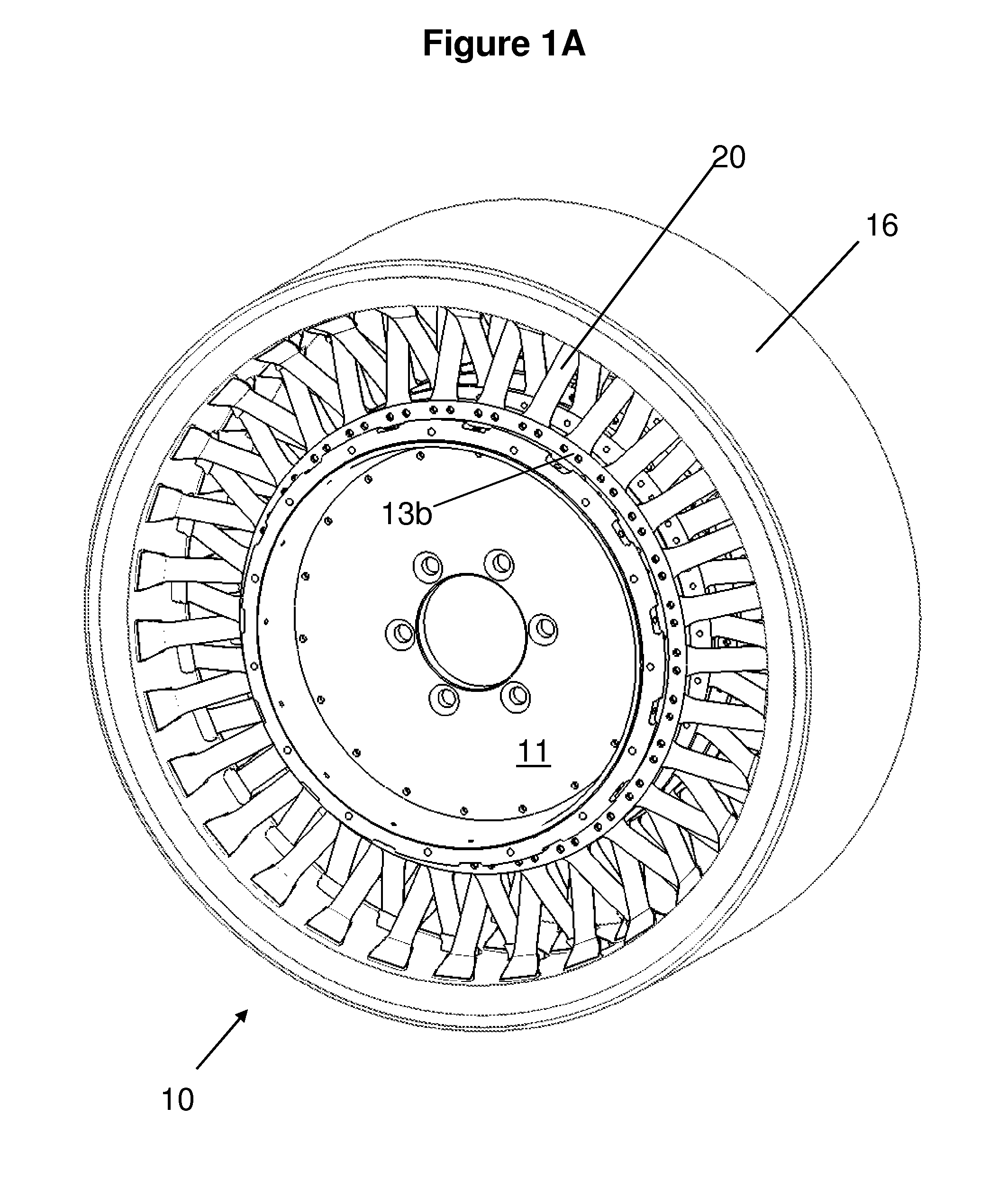
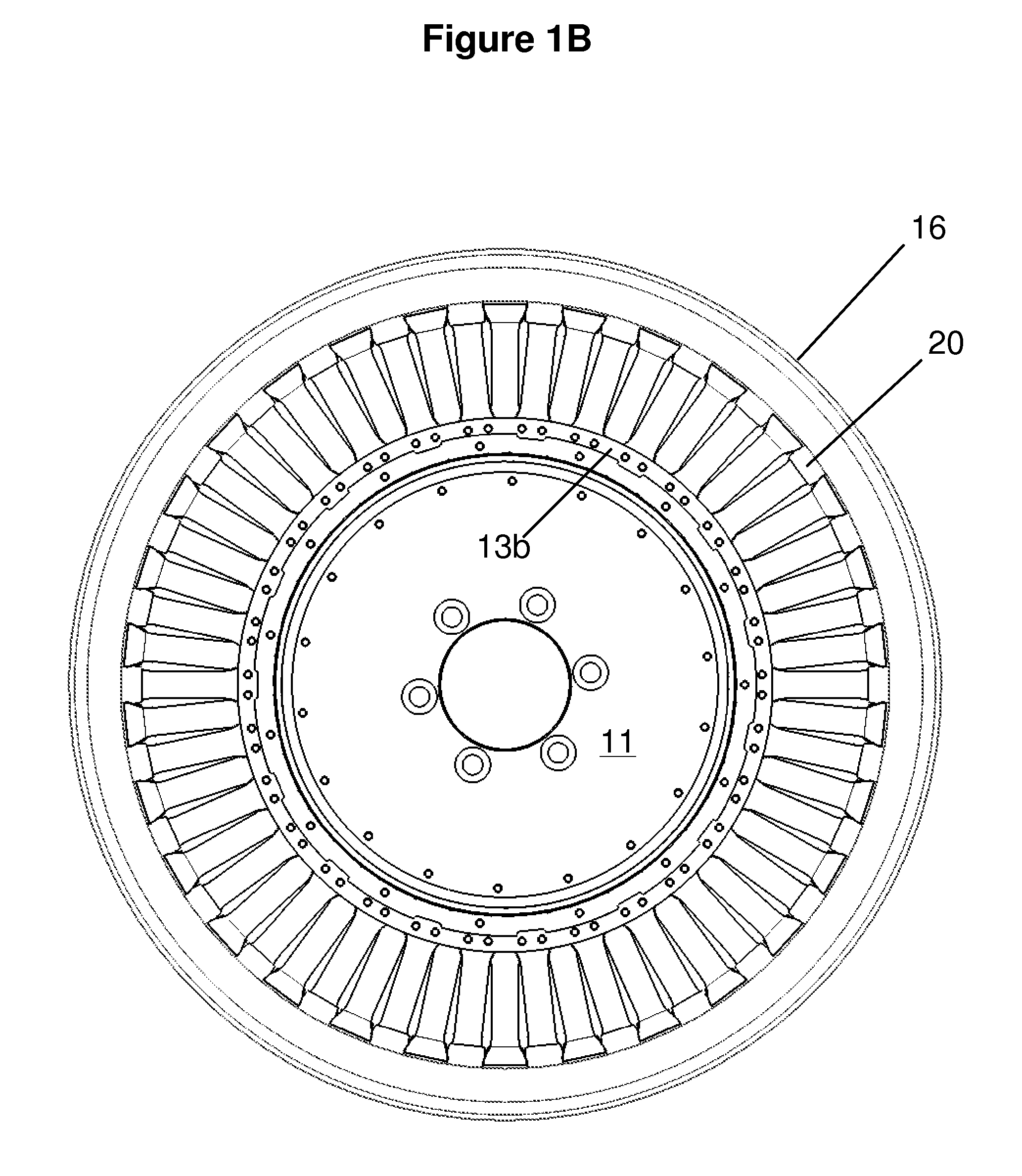
[0030]FIGS. 1A, 1B, 2, and 3 illustrate a first preferred embodiment of a variable stiffness wheel 10. The variable stiffness wheel 10 includes a rim 11, fixed flanges 12b and 13b and movable flanges 12a and 13a (also referred to as rings, plates and collars in this specification), and a plurality of wheel segments 17, 18 (e.g., two oppositely angled spokes 20) engaged with the flanges 12a, 12b, 13a, 13b and an outer traction element 16.

[0031]The rim 11 includes an inner flange (not shown) which locates an adaptor plate and thereby allows the wheel 10 to be mounted on a spindle (not shown) which allows the variable stiffness wheel to rotate about the center axis. Preferably the spindle and mounting mechanism is similar to wheel mounting mechanism of present vehicles (e.g., secured by lug nuts). While the variable stiffness wheel 10, as well as other embodiments of the present invention, are described as being used on a vehicle, it should be understood that these embodiments can be u...


PUM


Abstract

A system for adjusting the compliance of a wheel is provided. In one embodiment, wheel segments are adjusted, causing the stiffness of the wheel to change. Such adjustments can be made while the wheel is rotating, allowing the wheel compliance to be changed while a vehicle is in motion.

Description

RELATED APPLICATIONS[0001]This application is a continuation-in-part of International Patent Application No. PCT / US05 / 15478, International Filing Date 13 Jun. 2005, entitled Variable Radial And / Or Lateral Compliance Wheel; and claims priority to U.S. Provisional Application Ser. No. 60 / 869,714 filed Dec. 12, 2006 entitled Variable Compliance Wheel, both of which are hereby incorporated by reference.BACKGROUND OF THE INVENTION[0002]The present invention generally relates to a wheel with variable compliance having many applications, including ground vehicle wheels, printing press rollers, material processing and handling equipment. More particularly, the present invention relates to a wheel that includes a rim having a center axis of rotation and a plurality of wheel segments engaged with the rim and connecting to a radial band appropriate for the intended usage of the wheel, where the rim and plurality of wheel segments are adapted to rotate about the center axis, and where the attac...

Claims


Application Information

Patent Timeline
Patent Type & Authority Patents(United States)
IPC IPC(8): B60B9/04
CPCB60B9/04B60B9/26B60C19/00B60C7/18B60C7/14
Inventor ANDERFAAS, ERICMILLER, BRIANBANKS, DEANCHARLAND, JONCLEMENS, DAVIDCULBERTSON, CHRISLENOACH, PETERTRAUERNICHT, JARED
Owner MILLENWORKS
Why Eureka
Try Eureka